Electrical system testing techniques
Key Highlights
- Always verify battery capacity under load rather than relying solely on resting voltage to prevent misdiagnosis.
- Use voltage-drop testing to identify high resistance in power and ground circuits, ensuring proper circuit function under load.
- Check shared sensor supply rails, like 5V references, for shorts or grounding issues that can cause multiple sensor failures simultaneously.
- Apply systematic testing — such as relay control and circuit load checks — to narrow down fault locations efficiently.
- Remember that complex vehicle issues often stem from simple electrical fundamentals, making mastery of these basics essential for accurate diagnosis.
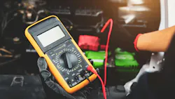
Electrical troubleshooting can be daunting, but when you understand how a circuit is designed, what each part is supposed to do, and why the system responds the way it does, you can break the circuit down and build your own test plan instead of leaning only on a trouble tree that may or may not lead you to a solution. In this article, I want to get back to the basics that still solve most of the electrical problems rolling into my shop: battery capacity under load, voltage-drop testing, shared sensor supply rails, and a practical crank/no-start example using a relay breakout tool.
Why electrical fundamentals still matter
Proper electrical testing gives technicians a clearer view of the fault the vehicle is presenting. Validating power to a device means confirming both the source voltage and the ground path. That device might be a module, actuator, relay, solenoid, sensor, switch, motor, or something else entirely.
During vehicle design, engineers do not simply ask whether a device works; they also ask how it could fail, what the effect of that failure would be, and how the system should respond. That design process is Failure Mode and Effects Analysis, or FMEA. For those of us in the bay, the useful takeaway is simpler: a diagnostic trouble code or limp-home symptom is often the module's planned response to a bad input, not the root cause itself. Substituted or default scan-tool values may look "normal" while the physical circuit does not. I have chased my share of those. Keep that in mind, then prove the circuit with meters, loads, and diagrams.
The fundamentals below are what make that proof possible.
Battery foundation: Voltage is not capacity
Every electrical test plan in my shop starts at the battery. Resting voltage alone is not enough. A battery can show about 12.6V at rest and still collapse when a starter, fuel pump, cooling fan, or a pile of modules draw current. What matters under load is the battery's ability to deliver current while holding voltage in a usable range. Shop language often calls this capacity, reserve capacity, or cold cranking amps (CCA). Whatever term the tester uses, the point is the same: open-circuit voltage does not equal the ability to support the circuit under load.
Before chasing a "bad module" or "bad ground," confirm the electrical foundation. Measure resting voltage after the vehicle has sat, then watch voltage while cranking or while a known heavy load is commanded. A healthy system typically holds cranking voltage in a range the modules can tolerate. If voltage collapses hard, every other reading becomes suspect. Sensor supplies can brown out, relays can chatter, modules can reset, and communication can drop. Those look like complicated electrical failures when the real problem is a weak battery, a poor cable connection, or high resistance in the main power path on the positive or negative side.
Also remember that a recently charged battery can mask a weak cell for a short time. If a vehicle arrives on a jump pack or after a long charge, recheck battery condition after a controlled discharge or after the vehicle has sat. Otherwise, you may validate circuits on a temporary voltage that will not be there on the next cold start. In fact, many of the faults we see today still stem back to the basics, and that begins with a sound electrical system that starts at the battery.
Voltage-drop testing under load
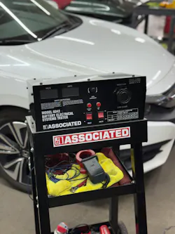
Starting at the battery, a good solid test is to apply a load to a fully charged battery that equals 50 percent of the rated CCA using a tester like the one shown in Figure 1. Compare the loaded voltage after 15 seconds to the chart shown on the machine. Typically, you want to see more than 9.6V.
Unloaded voltage will lie to you. Back-probing a connector with the circuit off, or with almost no current flowing, can show near-battery voltage even when the circuit cannot carry a real load. Voltage-drop testing answers a better question: how much voltage is being lost across a portion of the circuit while current is flowing?
Test both sides of the path. On the power side, measure from battery positive (or a known-good power source) to the power pin at the device while the device is operating. On the ground side, measure from the device ground pin to battery negative while the device is operating. The meter reading is the unwanted voltage lost to resistance in cables, splices, connectors, relays, fuse contacts, or ground eyelets.
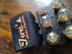
Keep the numbers practical. Many power and ground paths should show only a small drop under normal load. Exact limits vary by OEM and circuit, so use service information when it publishes a spec. The diagnostic idea is consistent: if the device is starved on the feed side or lifted on the ground side while it is working, the device is not seeing the voltage the battery appears to offer. That is why a pump, fan, or lamp can look "powered" with a test light or an unloaded meter and still fail in service. One tester I rely on is the Load It from Joe’s Auto Electric (Figure 2). This tool lets you load a circuit quickly, which streamlines the work.
Voltage-drop testing also keeps you honest about where to open the harness. If the drop is across a relay output, start there. If the drop is across a ground eyelet that serves several modules, you may explain multiple codes with one repair. If the drop only appears when the harness is moved, you have evidence of an intermittent high-resistance connection instead of a guessing game. Mastering these basics requires a solid foundation in basic electrical skills and Ohm's Law, because those fundamentals remain critical even when the vehicle is full of modules and networks.
Sensor supply rails: Shared 5V and collateral damage
Many sensors do not run directly from battery voltage. The control module provides a regulated reference supply, commonly 5V, sometimes 3.3V or another rail depending on the design. That rail is a clean, limited supply used by one or more sensors so the module can interpret their signals against a known reference.
The important detail is that rails are often shared. A throttle position sensor, accelerator pedal sensor, manifold pressure sensor, or other inputs may tap off the same 5V supply and sensor ground inside the module or within a harness splice. If one sensor develops an internal short from the 5V pin to ground, or if the 5V wire is pinched to ground, the rail voltage can collapse. Every sensor on that rail may then read incorrectly at the same time. The scan tool can show a cluster of unlikely failures, and the temptation may be to start replacing parts, which technicians should always avoid. Again, the goal is to always test it out and prove the failure.
Prove the rail circuit before you replace parts. Measure the 5V reference at the module connector and at the sensor connector with the circuit powered. If the rail is low everywhere, look for a shorted sensor or a grounded supply wire. A practical method I use is to watch the rail voltage while disconnecting sensors on that supply one at a time. If unplugging one sensor restores the rail, that sensor or its immediate wiring is pulling the supply down. If the rail stays low with the sensors disconnected, focus on the supply wire, splice, or the module itself.
Also verify sensor ground. A poor sensor ground can shift every signal on that ground and create the appearance of multiple failed sensors. Compare sensor ground to battery negative with your DVOM in voltage measurement mode under operating conditions. What you see is voltage drop. On a working sensor ground, I usually expect a small reading, often under about 100 mV. A hard zero can mean you are not actually loading the circuit, not that the ground is perfect. If the voltage is high, then you generally have high resistance in the circuit under test, and you’ll need to chase it down. When a shared rail or shared sensor ground is the root cause, the repair is usually one connector, one shorted component, or one damaged wire, not a handful of unrelated sensors.
Diagnostic techniques: Crank, no-start example
A practical way to apply this thinking is a vehicle that has been towed in with a crank, no-start condition. The first goal is not to identify the failed part immediately. The first goal is to gather information that separates the fault into a smaller system. Confirm that the engine cranks at normal speed, note warning lamps or security indicators, listen for the electric fuel pump during key-on or power-up, and do a quick visual inspection.
Do not skip the visual inspection. Seemingly unrelated items can take you down a rabbit hole. Water intrusion in lighting or blind-spot modules can take down a network. Rodent damage, chewed wiring, disconnected intake ducting, damaged connectors, blown fuses, impact damage, or road debris near fuel and wiring harnesses can all create a crank, no-start. These observations keep you from chasing scan data while overlooking an obvious physical cause.
Once the basics are gathered, start developing intelligence on the no-start. A gasoline engine needs the right air-fuel mixture, ignition, compression, and timing. For a quick first split, ask: does the engine appear to be missing fuel, or does it appear to be missing ignition? That question prevents the diagnosis from spreading across every sensor, module, or wiring path.
One fast way to assess a suspected fuel issue is to introduce a controlled external fuel source, such as propane, into the intake while cranking. If the engine briefly fires or runs while propane is metered in, the engine has enough spark, compression, and timing to support combustion, and the path should move toward fuel delivery. Perform this carefully with controlled flow, proper ventilation, and awareness of fire risk. Used correctly, it can also help a disabled vehicle run briefly enough to aid with vehicle movement.
If the engine responds to added fuel, the next question is how the vehicle controls fuel delivery. In many applications, the in-tank fuel pump is a brushed DC motor inside a fuel pump module. The pump may be supplied by a relay, fuse, control module, or fuel pump driver depending on the design. Many systems still use a fuel pump relay for main pump power while the pump ground is tied to chassis ground.
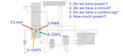
At this point, choose test points that give the most information with the least disassembly. Going straight to the fuel tank connector may seem logical, but on many vehicles that connector is harder to access than the relay, fuse, or fuel pump control point. A fuse loop, DVOM, and current probe can place you on the working side of the circuit without disturbing the tank. Better yet, if the control relay is accessible, determine whether main power is available, whether the relay is being commanded, whether voltage is leaving the relay, and whether current is flowing through the pump circuit. Looking closely at the diagram from a 2022 Honda Civic (Figure 3), we can see who does what and where the failure points potentially are.
A relay breakout device (Figure 4) is especially useful because it separates the circuit into testable sections. You can verify the load-side power feed, see whether the relay control side is being commanded, and manually close the load side when appropriate. Some breakout tools include LEDs or an audible indicator to show circuit activity. If battery voltage is available at the relay and the relay is commanded, but the pump does not run, the next question is whether current is flowing to the pump. No current flow may point toward an open circuit, poor connection, or an open pump motor. Excessive current or a fuse that opens may point toward a shorted pump, damaged wiring, or an overloaded circuit. If the relay is never commanded, move to the control side of the relay, module command, crank signal, security status, or other enabling conditions.
Looking back at Figure 3, let’s break down the relay pins in our example diagram:
- Main Device Power Supply
- Relay Main Power Out
- Positive Relay Control Feed
- Negative Relay Control (switching circuit)
Most relays follow DIN 72552:
- 30: Main Device Power Supply
- 87: Relay Main Power Out
- 85: Positive Relay Control Feed
- 86: Negative Relay Control (switching circuit)
Now keep in mind that you should always reference the wiring diagram for the vehicle under test. Some manufacturers control the relay by switching the high side or the low side of pins 85 and 86. Additionally, I have seen pins 30 and 87 switched. This is where a breakout device with colored LEDs can help sort this out.
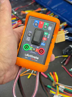
With the breakout device shown in Figure 4, confirm main power at the relay with a DVOM connected to the proper 4 mm banana jack, then use the breakout tool to interrogate the load side of the circuit through the two-way switch on the side of the device. Pushing the switch up engages the bi-colored LED to provide information as to which terminal has power for the relay to deliver to the device. A red LED indicates that pin 30 is the feed, and a green LED indicates that pin 87 is the feed. If the light does not come on, then we are either missing power or have an open circuit on the load side.
You can also momentarily energize the pump side of the circuit and evaluate circuit connectivity through the load to ground. If the tool indicates power is present, but the pump does not respond, suspect excessive resistance, an open in the working side of the circuit, a poor ground path, or a failed pump motor. If the tool has an audible function, it can be used while gently moving harnesses, tapping the fuel tank, or lightly disturbing suspect areas to expose an intermittent connection. The tool shown in Figure 4 has such a feature; check out the user manual for more details. The purpose is not to force the circuit to work, but to watch for a reaction that points to where the circuit is losing integrity.
This approach keeps the diagnosis organized. You are not testing randomly; each test is designed to answer a question. Is the battery able to support the load? Is voltage being lost across the power or ground path? Is a shared sensor rail collapsed? Is the engine capable of running on an added fuel source? Is the fuel pump being powered? Is the relay being commanded? Is the pump circuit carrying current? Is the ground path able to support the load? By answering these questions in order, you build a diagnostic path from symptom to system to circuit to component.
Closing thoughts
Before you replace the next sensor or module, run through the basics:
- Confirm battery condition under load, not just resting voltage.
- Voltage-drop test power and ground while the circuit is working.
- Measure shared sensor rails (often 5V) and watch for one shorted sensor pulling the rail down.
- Separate protective module strategy and substituted data from the physical fault.
- Use the diagram, choose accessible test points, and let each measurement answer one clear question.
Electrical diagnosis gets easier when the fundamentals come first. Capacity, voltage drop, and reference rails explain a large share of the weird electrical failures that otherwise turn into a parts-cannon exercise. These skills will pay off as vehicles continue to get more complex, because the basics still get you to the root of the problem.
About the Author
 Scott Brown
Scott Brown
Founder - Diagnostic Network
Scott is an ASE Master Certified Automobile Technician with L1, L3, & L4 credentials and has over 39 years of professional service industry experience. As an independent shop owner in Southern California and with his engagement at various levels of within our industry, he continuously strives to move the industry forward through networking, education, communications, and training. Scott is a founder of the Diagnostic Network (https://diag.net/) which was born in 2018 after he retired after 22 years at iATN, where he served as company president.
Brown is also the host of Professional Tool and Equipment News (PTEN) and VehicleServicePros.com podcast, Torque Factor. The podcast addresses the latest automotive service technologies while focusing on expanding knowledge and awareness around tools, equipment, education, and industry trends.