Editor's note: Due to a production error, this article appeared incomplete in the December 2023 print edition of Motor Age. The complete version is available below.
So, you’ve done your due diligence and have attended many an electrical course. You’ve invested in yourself and your career and have acquired the proper tools to get the job done right. So, why is it that you're struggling with electrical fault-finding?
So many times, I’ve faced disheartened technicians. They looked as if they’d lost their best friend. When inquiring with them what the issue might be, they’ve responded with, “I just can't seem to get it. Why does electricity always seem to kick my butt? It makes perfect sense in class but when I put it to use in the shop, it all seems too wrong?”
Well, I’ve been there before, and it's not fun. In fact, a series of misdiagnoses or comebacks is all it takes to knock the wind right out of a technician’s sail. But it’s not from a lack of trying. What many take for granted is the location of their chosen test point (relative to the circuit, as a whole) is not revealing the entire story.
Loaded/dynamic testing
This is a huge oversight that many technicians still don’t consider. The difference between testing a circuit dynamically versus when it is open is the difference between truly locating the problem and hoping the open-circuit test reveals the fault.
What I'm getting at is as follows:
When a circuit has been opened and an ohmmeter is used to evaluate the health of a component or related circuit, that ohmmeter is simply checking continuity. In other words, is there a completed path between the two test meter leads and the points in the circuit they are both referencing? If there is a gross failure, it might be detected by the ohmmeter (with a continuity/resistance test) but that is not a likely scenario.
The reason is an ohmmeter doesn’t “load” the circuit like when the circuit is functioning under its intended design. An ohmmeter places a very small current in the section of the circuit being tested. This current is typically far less than that of a circuit under normal operation.
As current flows, voltage will drop (the basis for Ohm’s law) because all portions of a circuit have resistance (Figure 1). Regardless of how much or how little resistance, the voltage will always drop (proportionally to the circuit resistance) across two test points in a resistance test. This is because there is a relationship between resistance, voltage/voltage drop, and current flow.
- If resistance is fixed, current will increase with voltage increase
- If voltage is fixed, current will decrease with added resistance
- If the current is fixed, the voltage will drop with an increase in resistance
The ohmmeter uses that voltage drop (and Ohm’s law equation, Figure 2) to calculate resistance.
Now, because no current is flowing through the circuit being measured when it is opened (during a continuity/resistance test) the circuit isn’t being loaded. You can picture this concept as a stress test that a cardiologist would perform on a person experiencing blood circulatory issues (Figure 3). It should be plain to see that a person’s cardiovascular system may function normally when the person is at rest but placed on a treadmill for a period of time, and the fault is likely flushed to the surface.
With that, it's far more accurate to test that circuit under loaded conditions. When a circuit is under normal operating conditions, it carries its intended current flow. But if there is a fault present related to the resistance of the circuit (the copper wiring) or the devices within that circuit, a voltage drop will occur; it's just plain old physics.
Testing locations
The basis for this entire article is right here. What you read above was a precursor to good testing techniques. As mentioned in the title, being in the right place at the right time is absolutely crucial for accurate fault detection in an efficient manner.
Keeping in mind that a circuit is either classified as one that performs work (like illuminating a light bulb, sounding a horn, or operating a motor) or one that does not perform work (simply carries a signal, like that of a crankshaft position sensor or fuel tank pressure sensor), we have to strategize to test in different locations depending on which circuit it is. This is best explained by way of real-world examples.
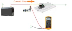
This is a simple and typical port fuel injector circuit (Figure 4). The current must flow through the injector properly for the injector to do its job and deliver fuel properly. As can be seen, the current leaves the battery and passes through the injector toward the path to ground (located externally to the PCM but switched internally to the PCM.)
Because voltage drops as it passes over resistances, we would expect the injector to use up (or drop) almost all the available voltage, leaving very little to drop across electrical connections or the switching device (the transistor or MOSFET) internal to the PCM.
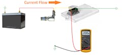
If one were to test the control circuit (when the injector is energized) at the back of the injector connector, one should anticipate reading near zero volts (reading in millivolts) (Figure 5). If the meter test lead were then positioned to take that same measurement at the injector control circuit of PCM, again one should anticipate near zero volts (Figure 6).
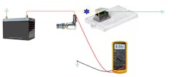
Now, let's change the scenario a bit. Perform those same measurements with a fault present in the circuit (blue star). When testing at the same injector connector terminal, there is still voltage available. This reading should alert you of a resistance issue somewhere downstream of the injector (between your test point and the ground point of the circuit (Figure 7).
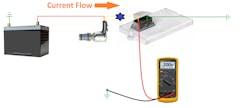
However, If you made that same measurement at the PCM, you would still see nearly zero volts, not readily alerting you to a fault (Figure 8). So, did the test let you down? Is the test result a lie? No, and no. We must ALWAYS consider the limitations of the tool we are using and the test we are performing. The test measures the available voltage at the test point. At that point, we measured near zero. That is the absolute truth. What the test cannot tell you (its limitation) is that some of the voltage was dropped across the injector (the intended load) and the rest was dropped across the green corrosion in the injector control wire.
When using a voltage test on a non-work-performing circuit (a signal circuit) I want to test as close to the receiving/processing computer as possible. For instance, just because a signal was output from a crankshaft position sensor properly doesn’t mean it made it to the ECU unscathed.
To sum it up, when using only a voltage test on a work-performing circuit, I perform the test as close to the load device as possible. I simply want to see if the intended load is using all the voltage or not. When testing.
Overcoming test limitations
Clearly, the above test was not ideal for the scenario. But that’s okay, as long as we are aware of what the test can reveal to us and what it cannot reveal to us. The real question is how can potential mishaps like that be avoided altogether? Consider implementing a different version of the same test.
I would describe the previous testing technique as an “available-voltage test.” A true voltage-drop test means letting the meter do what it does as a voltmeter. It displays the potential indifference between the two test leads. Creating a series of tests by placing the test leads across different sections of the circuit would’ve revealed the fault and its location to us.
For instance, placing the meter leads across the injector (with the same fault present as described earlier) would show the injector only using some of the voltage (not “almost all” the voltage, as it should). This reveals a problem is present, but it doesn’t yet tell us where the problem is located. Moving the meter leads to different sections of the circuit is then required to find the location of the voltage drop (Figure 9).
Here is another technique altogether. I’ve discussed many times using a current probe to measure amperage flow. The current probe measures the “work” being performed by the circuit. If nothing is wrong, we should anticipate normal amperage values. However, if there is any added resistance/voltage drop anywhere in that circuit, the current probe will reveal a lack in current value (less work being performed).
The current probe can be coupled to a DVOM, can be used stand-alone (depending on if it’s designed with its own display), or it can be coupled with a digital storage oscilloscope (DSO). I highly recommend the latter as the lab scope affords us a few opportunities here.
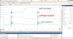
The DSO allows us a visual interpretation of electrical current flow meaning not only can we see the work being performed but also how well (or how poorly) the work is being performed over time (think “heat-buildup”). It also allows us the opportunity to view multiple channels (or aspects of the circuit) at the same time. With the faulted example earlier, we can now look at these four different aspects, for instance (Figure 10):
- Voltage feeding the injector
- Voltage on the control-side of the injector circuit (back probed at the injector connector)
- Voltage on the control-side of the injector circuit (back probed at the PCM connector)
- Circuit current
This simple yet complete view of the entire circuit simultaneously not only easily revealed an issue was present but also where in the circuit the fault was located. A voltage drop existed on the voltage-feed side of an ignition coil due to a spread terminal at an inline connector. This is revealed by the lack of current amplitude.
As the current began to flow, voltage started to drop, leaving a lack of available voltage feeding the ignition coil. This was the cause of a misfire under loaded engine conditions but was quite simple and quick to discover. I love it when a good plan comes together.
The experiment
So, what I don’t want you to do is take my word for it. I want you to conduct an experiment for yourselves and I'd like you to contact me with your conclusions ([email protected]). I want you to research a simple circuit in a wiring diagram. I then want you to print out that diagram (so you can annotate it). Conduct the tests I described above for yourselves and document the measured voltage at the test points called out early (regarding the work circuit).
I have a strong feeling you will be pleasantly surprised by how easy it is with a little bit of practice. Once these tests and techniques are mastered, they can be applied to any circuit on virtually any vehicle you encounter, making you the go-to tech for electrical fault finding.
Let me leave you this question. How would it feel to actually be profitable with electrical diagnostic work? There is only one way to find out. I hope I’ve empowered you to implement my suggestions. I am really looking forward to reading about all your success stories.
About the Author
Brandon Steckler
Technical Editor | Motor Age
Brandon began his career in Northampton County Community College in Bethlehem, Pennsylvania, where he was a student of GM’s Automotive Service Educational program. In 2001, he graduated top of his class and earned the GM Leadership award for his efforts. He later began working as a technician at a Saturn dealership in Reading, Pennsylvania, where he quickly attained Master Technician status. He later transitioned to working with Hondas, where he aggressively worked to attain another Master Technician status.
Always having a passion for a full understanding of system/component functionality, he rapidly earned a reputation for deciphering strange failures at an efficient pace and became known as an information specialist among the staff and peers at the dealership. In search of new challenges, he transitioned away from the dealership and to the independent world, where he specialized in diagnostics and driveability.
Today, he is an instructor with both Carquest Technical Institute and Worldpac Training Institute. Along with beta testing for Automotive Test Solutions, he develops curriculum/submits case studies for educational purposes. Through Steckler Automotive Technical Services, LLC., Brandon also provides telephone and live technical support, as well as private training, for technicians all across the world.
Brandon holds ASE certifications A1-A9 as well as C1 (Service Consultant). He is certified as an Advanced Level Specialist in L1 (Advanced Engine Performance), L2 (Advanced Diesel Engine Performance), L3 (Hybrid/EV Specialist), L4 (ADAS) and xEV-Level 2 (Technician electrical safety).
He contributes weekly to Facebook automotive chat groups, has authored several books and classes, and truly enjoys traveling across the globe to help other technicians attain a level of understanding that will serve them well throughout their careers.


