Electrical circuit testing techniques for service technicians
In my humble opinion, technicians must have a firm understanding of automotive electrical circuits so when problems surface, testing techniques can be leveraged to realize success.
In this article, we’ll take a deep dive into the core techniques of electrical circuit testing. From reading wiring diagrams, accessing component locators, sourcing connector charts, and selecting the right tools, we’ll cover them all. After reading this article, you should have a sharper focus on the art of electrical circuit testing, which I know will add to your technical proficiency and ability to easily earn more money.
Regardless of your experience level, we can all learn something new every day.
Fundamental concepts: Electrical basics
Technicians must possess a solid understanding of voltage, current, resistance/load, and how their interactions can lead to proper system operation or how a failure in any of those can cause havoc within automotive circuits.
Voltage is the electrical force, and without the right amount, an electrical circuit cannot function properly. This is one of the main reasons battery testing should be carried out proactively, like during a service visit. In my shop, we test the low-voltage battery during every vehicle service visit. Replacing batteries before they cause havoc saves in multiple ways.
Current is the flow of electrons from the power supply. Circuits are designed to support a specific range of current at the operating voltage. Although current measurements are not super common, they can be very revealing, especially when viewed through the eyes of an oscilloscope.
Resistance is the opposition to current flow and comes in a few flavors. Every connection, length of wire, switch, relay, etc. provides a small, tolerable amount of resistance. Each point of resistance limits current by consuming some of the electrical supply voltage. For a circuit to do its job, the primary consumption of the supply voltage needs to be consumed by the load. Whether the load is a taillight, window motor, or fuel injector, minimal voltage drops should exist within the circuit so the full electrical force is available to perform the task at hand.
Tools for success
One must be very acquainted with their test equipment. First, a digital volt-ohm meter (DVOM) is a pretty standard piece of equipment a technician needs to have easy access to if they are going to be successful. However, one also needs to be keenly aware of the device's limitations and its behaviors.
One behavior that comes to mind is auto-ranging. If one is not paying close attention, this feature can fool you. And because of this, I find myself typically turning it off and manually controlling the display resolution. This is done by knowing the expected range to focus on the circuit or device under test. For example, if a meter is constantly changing its display scaling, observing the numbers can be annoying. This is also true with some oscilloscopes that have auto-ranging on by default.
Second, a test light is very useful at times, and I find myself using it often. In fact, just this week, I was working with one of our apprentices who was faced with a parasitic load that was measured out at just under 500mA. As we discussed strategies for locating the source, I suggested that we start at the easiest point of access, which was at the under-hood power distribution center. As I was guiding her through the strategy of my approach, I explained that there were a few ways we could begin testing.
One strategy was to begin removing fuses until the draw disappeared. However, since there were many fuses in that power distribution center, we could narrow down the list of fuses to pull by utilizing a test light.
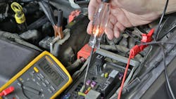
After verifying that the test light was working, we began identifying the fuses that were connected to battery power by marching up and down the fuse block noting which fuses were connected to battery power (Figure 1).
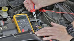
Then, all we needed to do was start removing each of the identified fuses one at a time while watching our DVOM. At about the third fuse we pulled, we noticed that our load dropped to around 7mA (Figure 2).
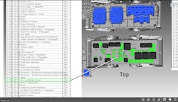
Looking at the label under the fuse block cover, we found that the fuse we needed to identify service information on was fuse 173 (25A). Digging into service information revealed that the only device protected by that fuse was the ABS module (Figure 3).
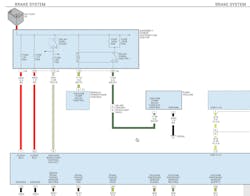
Next, we looked at the wiring diagram (Figure 4) and found that there were two continuous power supplies protected by two different fuses, one of which was the fuse supplying the parasitic load. We also wanted to check the ignition feed to the ABS module to make sure that we didn’t have a short to power on that circuit with the key off. We confirmed this by measuring the signal at pin-8 of the ABS module for the absence of power with the key off.
This vehicle indeed needed a new ABS module. When interviewing the clients, they revealed to us that they have had the battery replaced in the vehicle about every 18 months. Today, it’s not uncommon to see a 12V battery requiring replacement every three to five years. If only the parasitic load had been discovered previously, the client likely wouldn’t have had so many battery failures.
There are other ways to identify which fuses are likely supporting an unwanted parasitic load. One test involves measuring the voltage drop across the fuse. As mentioned earlier, all connections will have resistance, and therefore a voltage drop can be observed. If you find a fuse that has a voltage drop, then you can investigate items protected by that fuse. You might want to consider this style of test to avoid the possibility of waking up a module after removing and reinstalling a fuse. If such an event occurred, it would result in lost time as you would be waiting for that module or device to properly power down.
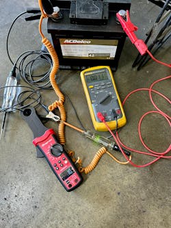
Now looking back at Figures 1-4, one should also have an awareness of the amount of “load” your test light places on a circuit. Measuring the current your test light/s draws is very good for reference. This can be useful information especially when trying to load test low current circuits, either the power or ground supply where you suspect unwanted resistance. In some cases, you may need to make up your own set of test lights for these tasks. Personally, I have several lights ranging from 11mA up to 8A.
One quick test you can deploy for this is when you are checking for power and ground on, say, a mass air flow sensor. If you are using a DVOM and back-probing the sensor with it disconnected, you are not loading the circuit. With high resistance upstream on the power side, you might see 12.2V KOEO (key on, engine off) across the power and ground, but if you were able to take a test light that drew at least 500mA and connected the ground side of the test light to the battery negative and touched the probe side to the positive lead on the meter, the light would not light and you would see your meter drop as well. This is how you can leverage test lights to help you load a circuit and why it is important to know how much current your light draws. For example, I have a test light with an LED. This light only draws 11mA, and it is possible that this amount of load would be unable to allow this theoretical voltage drop to reveal itself as shown in Figure 5.
Third, I consider a current probe to be a valuable tool, one I recommend and use often. Pairing it with a voltmeter will provide one with some valuable information about the total power consumption in the system under test. Power is expressed in wattage, which is what we’re usually accustomed to in our homes when replacing light bulbs. This too is something we should be familiar with since there are systems on cars that monitor current flow, and if the normal amount of current is deviated from, other problems can surface. For example, some vehicles monitor the external lighting system, so if a low-current LED bulb is installed in place of an incandescent, warning lights or messages are likely to show up. These systems usually deploy a precision resistor within a module connected to the power supply side of the bulb circuit. This resistor will provide a known voltage drop when the circuit is consuming the design current. If you install a bulb that takes it outside of the calibrated current consumption range -- think LED -- this will result in that module communicating this error through a warning light or message for the driver.
Current measurements
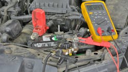
I would like to start with the fact that inductive current probes have limitations and reemphasize that one needs to know their tools and behaviors. A handheld inductive current probe can be a valuable tool when used correctly. If you are trying to measure/validate a parasitic load with a current probe, you are likely going to be misled. The reason I say this is from experience. When I am performing parasitic load testing on a vehicle, I am always going to base my conclusions on a direct series measurement through my DVOM. When you perform a parasitic load test, the best practice is to properly configure the vehicle for monitoring. Connecting a high current switch between the battery ground post and cable (Figure 6) will allow you to carefully monitor parasitic load activity after a proper vehicle shutdown.
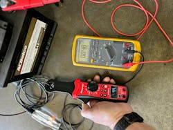
Additionally, as mentioned earlier, inductive current probes can give inaccurate results at very low currents. Most probes will require that you hold the probe very near the point of measurement when turning the device on so that you can obtain a zero-baseline reading. Then carefully maneuver the probe over the circuit to monitor. Your results may vary and change over time, which will require you to remove the probe and re-zero repeatedly. (Please refer to the manual that came with your current probe.) This is because of the varying magnetic fields near the probe. Figure 7 demonstrates some of the testing performed in preparation for this article.
Current probes and oscilloscopes
I first saw the power of a current probe coupled with an oscilloscope back around 1990 on the “For Techs Only” forum on CompuServe. The person showing this technique was looking at an ignition module controlling waste-spark coils. Two out of the three coils had a ramp up to the current-limiting point. The other was missing the ramp and looked more like a square wave. Initially, I didn’t believe what I was seeing until I learned more about this technique. Since then, I have been using current probes regularly as a tool to analyze everything from coils, fuel injectors, blower motors, and more.
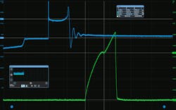
I’ve shared an example (Figure 8) of a current pattern from a fuel injector (green trace). If you look closely, you’ll see my cursors being used to measure not only the time it took for the injector to fully open by noting the injector pintle hump but also the amount of current flow to make this happen.
Driveability and performance
Over the years, I have worked on many Corvettes, and back in the 1989 era, the Tuned Port powerplant had plenty of fuel injector issues. Many of these issues were inherent with the Rochester Multec injector. While most of these vehicles are no longer in service due to age and environment, we still see them from time to time. Recently, we had one in that had various driveability complaints such as extended crank times and a rough idle. Occasionally, the vehicle would exhibit a slight hesitation upon throttle tip-in. During my analysis, I wanted to take a close look at the fuel injectors. Since this is a bank-fired system, we know that the injectors are wired in parallel groups. Each of the two groups is protected by their own fuses. This is good for us since this allows us to simply install a fuse loop so that we can attach a current probe and make an observation.
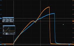
Figure 9 demonstrates the before and after injector performance once new injectors were installed.
As you can see, the new injectors' orange trace has a very distinct injector pintle opening signal versus the old Multec injectors occurring later in time. The vehicle’s driveability symptoms have diminished, and every time we see the client, he raves about how well his vehicle is performing.
Case study: Crank no-start
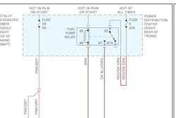
A 2009 Dodge Challenger was towed in after the client experienced a crank no-start event. We proceeded to perform our standard routines for such a symptom, which led us to believe that the fuel pump was highly suspect. Looking for a way to test it electrically, we found that there is a power distribution center located in the trunk possessing the fuel pump relay.
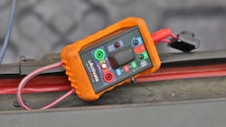
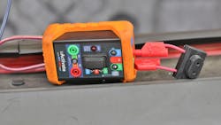
This location provides a great access point for testing both the fuel pump relay control signal and power flow through the fuel pump. One test device I have relied on over the years is the uActivate from AESwave. Recently, they updated the uActivate with a few new features. One of the features is a new momentary push-button on the side of the unit that helps you understand which terminal (87 or 87A) carries the load. When I installed the device in place of the relay, the first test I performed was to have an assistant power cycle the key while observing the LED indicator placed across pins 85 and 86 (Figure 10).
Since I was able to confirm proper ECM control of the fuel pump relay, I moved on to my next test. Referencing the wiring diagram (Figure 10), we can see that pin-30 is our power supply and pin-87 feeds the fuel pump. Pushing in on the momentary switch located on the side of the uActivate resulted in the LED under ID 87 to dimly light up. This immediately told me that there was a high probability of high resistance in this circuit. To confirm the upstream power supply, I connected a high current test light to the 4mm test plug on pin-30 at the top of the uActivate to ground where it lit. Next, I had an assistant help by tapping on the bottom of the fuel tank while I held the test button down and observed the LED under 87, where it momentarily flashed bright (Figure 11).
I then remembered that I made a request to Jorge Menchu, the founder of AESwave, a while back after explaining my desire to be able to perform this test without an assistant. He suggested that a small speaker could be deployed, which he proceeded to manufacture and send to me to test out. This worked out great because after inserting the speaker, I proceeded to repeat the fuel tank tap test and could hear the speaker come to life intermittently as the bottom of the tank was coerced. I have a short video of this activity (youtube.com/shorts/F_pveMSVNjQ). See Figure 12 where the speaker is installed.
Based on these observations, we were able to conclude that the high resistance was downstream on the pump side. Next, we confirmed our electrical connections at the fuel pump module were not the cause of the high resistance and concluded that the vehicle needed a new fuel pump module assembly.
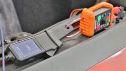
After the replacement of the fuel pump module, I decided to reinstall the uActivate and utilize the large current loop on the bottom of the unit to sample the fuel pump current while turning the pump on via the on-off switch located in the center of the device and letting it stabilize (Figure 13).
The current trace here shows (Figure 14) the stall current of the brushed DC motor hitting approximately 29A and the nominal current operating at approximately 9A. Additionally, I was able to place cursors to measure the time between one revolution of the pump and determine that the fuel pump is operating around 6,500 rpm.
Conclusion
As you can see having a strong understanding of electrical circuits and behaviors and a keen awareness of measurement devices, such as meters, scopes, probes, etc., one can gain an advantage when it comes to performing competent diagnostics on today's and tomorrow’s vehicles.
About the Author

Scott Brown
Founder - Diagnostic Network
Scott is an ASE Master Certified Automobile Technician with L1, L3, & L4 credentials and has over 39 years of professional service industry experience. As an independent shop owner in Southern California and with his engagement at various levels of within our industry, he continuously strives to move the industry forward through networking, education, communications, and training. Scott is a founder of the Diagnostic Network (https://diag.net/) which was born in 2018 after he retired after 22 years at iATN, where he served as company president.
Brown is also the host of Professional Tool and Equipment News (PTEN) and VehicleServicePros.com podcast, Torque Factor. The podcast addresses the latest automotive service technologies while focusing on expanding knowledge and awareness around tools, equipment, education, and industry trends.
