Drivetrain Dynamics: Understanding and Servicing Modern Mount Technologies
Key Highlights
- Early vehicle mounts primarily served to attach the powertrain securely, with little regard for NVH comfort, relying on simple rubber or steel supports.
- Rubber mounts revolutionized NVH control by absorbing engine vibrations, with material hardness tailored to balance vibration isolation and drivetrain control.
- Modern mounts incorporate complex materials and active systems such as hydraulic chambers, vacuum controls, and magnetorheological fluids to adapt to driving conditions and improve ride quality.
- Hydraulic mounts use internal chambers with hydraulic fluid to dampen vibrations, responding differently at various frequencies for enhanced comfort and control.
- Active mounts with electronic controls, including MR fluid systems, can adjust stiffness in real-time, providing optimal NVH reduction and drivetrain stability.
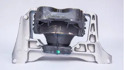
My first experience with a broken transmission mount came in high school. Being a high schooler in the mid-1990s, my friends and I primarily drove junk from the '70s and '80s. While square body pickups and Fox body Mustangs were popular choices, my personal favorite sub-$2,000 mode of transportation was the third-generation GM F-Body. Even a Z28 or Trans Am equipped with a tuned port injected small block couldn't be mistaken as fast, even to a naïve teenager. But they were good at converting rubber to smoke, and if equipped with an Auburn limited slip, they did respectable donuts. They were also equipped with either a BorgWarner T5 or a Turbo Hydra-Matic 700R4, with the latter being by far the most popular option—at least at the price point I was buying these vehicles at.
My friends and I learned quickly that if we played with the TV cable a bit, we could get that 700R4 to hold 1st gear longer. And under hard acceleration, when governor pressure finally overcame the throttle valve, the transmission would violently shift into 2nd gear, often with a coveted chirp of the rear tires. It was during one of these hard acceleration events that I experienced my first transmission mount letting go. When the vehicle hit the 1-2 upshift, I was convinced that the poor 700R4 had experienced an unplanned and rapid disassembly and was coming up through the tunnel in pieces to join me in the cabin. To say that the transmission and torque arm movement was violent would be a gross understatement. I was relieved when I discovered the vehicle still drove and shifted, and I learned a valuable lesson in the important role that engine and transmission mounts play.
We've Come a Long Way
When early automobiles first appeared on the road, engine and transmission mounts had one primary job: securely attach the powertrain to the chassis. Comfort and refinement were secondary concerns, and drivers expected vehicles to vibrate, shake, and transmit engine noise directly into the passenger compartment. Many early vehicles relied on rigid steel mounting points or very simple rubber cushions that provided little more than basic isolation.
As engine power increased and consumers began expecting quieter, smoother vehicles, engineers recognized that powertrain mounts could do much more than simply support weight. They became a critical component in controlling noise, vibration, and harshness (NVH). Engineers became focused on reducing unwanted sounds and vibrations while maintaining vehicle durability and performance.
The Rise of Rubber Isolation
The widespread use of natural rubber mounts represented one of the first major advancements in powertrain isolation. Rubber's elasticity allowed it to absorb engine vibration while still securely locating the engine and transmission within the chassis.
Engineers soon learned that not all rubber behaves the same. By altering the rubber compound and its hardness, manufacturers could tailor a mount's stiffness for specific applications. A softer mount provided excellent vibration isolation but allowed greater engine movement under acceleration and braking. A stiffer mount improved drivetrain control and handling but transmitted more vibration into the passenger compartment. Finding the proper balance quickly became one of the biggest challenges in mount design.
Synthetic Materials Improve Durability
While natural rubber performed well initially, manufacturers began replacing natural rubber with synthetic elastomers specifically engineered for automotive applications. Modern synthetic compounds offered significant improvements in resistance to petroleum products, high-temperature durability, long-term elasticity, and better fatigue resistance. These materials dramatically extended mount service life while maintaining consistent vibration isolation over hundreds of thousands of miles.
Engineering Around Frequency
One of the most significant advances in mount design came from a better understanding of vibration frequency. Low-frequency movement occurs during engine torque reactions, gear changes, and rapid throttle inputs, causing the engine to rock within the engine compartment. High-frequency vibrations originate from combustion events, rotating assemblies, and accessory drives. A conventional rubber mount optimized to control one type of vibration often performed poorly when exposed to another. Instead of simply selecting a harder or softer rubber compound, mounts were designed to target specific vibration frequencies.
Preparing for the Modern Era
Many of today's engine and transmission mounts now incorporate hydraulic chambers, vacuum controls, electronic actuators, or even magnetorheological fluids that actively alter mount stiffness based on operating conditions.
These technologies allow a vehicle to remain exceptionally smooth while idling at a traffic light, yet provide the rigidity needed to control drivetrain movement during aggressive acceleration or rapid shifts. As a result, modern mounts have evolved from passive support components into active participants in vehicle refinement and powertrain performance. Understanding how these technologies developed provides the foundation for diagnosing the increasingly sophisticated mount systems found on today's vehicles.
Hydraulic Engine Mounts
Hydraulic engine mounts represent one of the most significant advancements in powertrain isolation. While they appear similar to conventional mounts externally, their internal construction is considerably more complex. Instead of relying solely on rubber, hydraulic mounts incorporate chambers filled with a specially formulated hydraulic fluid. These chambers are connected by precisely engineered passages known as inertia tracks. Some designs also include flexible diaphragms or decoupler valves that alter fluid movement under different vibration frequencies.
As the engine moves, the rubber portion of the mount compresses, forcing hydraulic fluid from one chamber to another. The restricted movement of the fluid absorbs energy and dampens vibration much more effectively than rubber alone. One of the greatest advantages of hydraulic mounts is their ability to respond differently depending on vibration frequency. At idle, when low-frequency engine shake is most noticeable, fluid moves freely through the internal passages, providing excellent vibration isolation and significantly reducing the amount of engine movement transmitted into the passenger compartment. During rapid throttle changes or aggressive acceleration, fluid flow becomes restricted. The mount effectively stiffens, limiting excessive engine movement while maintaining drivetrain alignment.
Hydraulic mounts have become standard equipment on many passenger vehicles, luxury vehicles, and crossovers where refinement and passenger comfort is a major design priority. This also brings another level of complexity for NVH-compliant diagnostics for technicians. Common failures include fluid leakage, torn diaphragms, and internal chamber separation. Unlike solid rubber mounts, hydraulic mounts may appear visually intact while their internal damping characteristics have been completely lost.
Vacuum-Controlled Hydraulic Mounts
As manufacturers continued refining NVH characteristics, some introduced vacuum-controlled hydraulic mounts. These systems build upon the hydraulic mount design by allowing engine vacuum to alter the mount's internal stiffness.
A vacuum chamber inside the mount is connected to an electronically controlled valve. Depending on engine operating conditions, the Powertrain Control Module (PCM) commands vacuum to the mount, changing the position of an internal diaphragm.
Because the system continuously changes mount characteristics, it provides a noticeable improvement in both ride comfort and throttle response. Manufacturers such as Honda, Acura, Toyota, Ford, and Mazda have employed various versions of vacuum-controlled mounts over the years. These systems introduce additional diagnostic considerations. A mount may not be defective at all; instead, a cracked vacuum hose, leaking reservoir, faulty solenoid, or PCM control issue may prevent the mount from operating correctly.
Magnetorheological Fluid Mounts
One of the most advanced engine mount technologies currently available utilizes magnetorheological (MR) fluid, sometimes referred to as magnetic fluid technology.
Magnetorheological fluid consists of microscopic iron particles suspended within a synthetic carrier fluid. Under normal conditions, the fluid behaves much like conventional hydraulic oil. However, when exposed to a magnetic field generated by an internal electromagnetic coil, the iron particles rapidly align into chain-like structures that dramatically increase the fluid's apparent viscosity. And this transformation occurs in milliseconds.
By varying electrical current supplied to the electromagnetic coil, the control module can continuously alter the stiffness of the mount without any mechanical valves or moving hydraulic components. At idle, little or no magnetic field is applied, allowing the fluid to remain relatively free-flowing. The mount provides exceptional vibration isolation, minimizing engine shake and improving cabin comfort. During rapid acceleration, aggressive shifting, or high-speed cornering, the controller increases current to the electromagnetic coil. The MR fluid stiffens almost instantly, significantly reducing engine movement and improving drivetrain control. Unlike passive hydraulic mounts that rely solely on fluid flow characteristics, MR mounts can continuously adapt to changing driving conditions hundreds of times per second.
Several manufacturers have incorporated similar technologies into high-end luxury vehicles and performance applications, often alongside magnetorheological ride control systems. While these systems increase cost and complexity, they provide exceptional refinement without sacrificing vehicle responsiveness. Because these mounts rely on electronic control, diagnosis extends beyond simple visual inspection. A failed electromagnetic coil, damaged wiring, communication fault, or controller issue may prevent the mount from changing stiffness even though the mount itself remains mechanically intact. As electronically controlled powertrain mounts become more common, technicians must become comfortable diagnosing both the mechanical and electrical aspects of these systems.
Diagnostics Start with the Customer Complaint
Like any drivability concern, the diagnostic process begins with gathering as much information as possible. Ask the customer when the vibration occurs and under what conditions it's most noticeable. Is the vibration present only at idle, with the condition improving when engine speed increases? Is it most prominent on acceleration or deceleration? Or maybe it's only noticed when shifting or transitioning between drive and reverse? And don't overlook the obvious. Has there been recent engine or drivetrain work performed on the vehicle? The simplest explanation is often the correct one.
Consult service information. A technician can't diagnose a system without fully understanding it. Two minutes of research can save countless minutes of headache. It's also important to determine whether the customer is describing a vibration or a noise. Rattles, exhaust contact, and drivetrain clunks often originate from failed mounts but may have entirely different root causes.
Perform a Thorough Visual Inspection
The visual inspection remains one of the most valuable diagnostic steps. Inspect every engine and transmission mount for torn or separated rubber, oil saturation, fluid leakage, collapsed mount height, and rust jacking between bonded components.
Engine oil, transmission fluid, and power steering fluid can rapidly deteriorate many elastomer compounds. A mount that has softened due to prolonged oil exposure may allow excessive drivetrain movement even though the rubber hasn't physically separated.
Part of the visual inspection should include observation of engine and drivetrain movement. Carefully power brake the vehicle in both forward and reverse and watch for excessive engine roll, any sudden "jumping" motions, audible clunks, or metal-to-metal contact.
Moving Beyond the Visual
As powertrain mounts became electronically controlled, diagnostics have moved beyond mechanical inspection. Active mounts are going to rely on inputs. Remember, all a controller is doing is executing programming that says "if I see this, then I will do this." Verification of clean and correct information being fed into a controller is just as important as verifying the output being commanded is actually happening. Many active hydraulic mounts rely on engine vacuum, so it's important to verify vacuum is actually present and the PCM is commanding the system before replacing a mount. And don't forget the electrical side of the system. Battery voltage, wiring continuity, and ground integrity should not be overlooked.
Diagnosing Magnetorheological Fluid Mounts
Just like MR used in ride control componentry, MR mounts depend on an electromagnetic coil to alter the viscosity of the internal fluid. If that coil loses power, develops excessive resistance, or experiences an open or short circuit, the mount typically defaults to a passive state. Diagnostics should begin with the basics. Verify power and ground at the mount connector. Measure coil resistance and compare it to the manufacturer's specifications. Inspect all connectors for corrosion, damaged terminals, or moisture intrusion.
Often you can evaluate control strategy with scan diagnostic equipment. Many vehicles allow a technician to monitor command requests and duty cycle through live data, and in many cases allow the technician to actively command the mount through bi-directional control. Oscilloscopes can make quick work of monitoring the work being performed by monitoring control current through the mount.
More Than Just a Mount
Thirty years ago, a broken engine or transmission mount usually announced itself with a loud bang, excessive drivetrain movement, or an unmistakable vibration. While those symptoms still occur, today's mounts have evolved into highly engineered NVH components that play a critical role in vehicle refinement, drivability, and even electronic powertrain management. Whether constructed from molded rubber, hydraulic chambers, vacuum controls, or magnetorheological fluids, modern mounts do far more than support the engine. They actively shape the driving experience. As vehicle technology continues to advance, technicians who understand both the mechanical and electronic operation of these systems will be better equipped to diagnose vibration complaints accurately, avoid unnecessary parts replacement, and deliver repairs that restore the smooth, refined performance customers have come to expect.
About the Author
 Erik Screeden
Erik Screeden
Technical and Multimedia Content Director
Erik Screeden is the Technical and Multimedia Content Director for the Vehicle Service & Repair Group. Erik is an ASE Master Automobile Technician with L1, and L4 credentials, who has been in the industry for over 25 years in various capacities. During that time, Screeden was a technician. He started out at a Ford dealership and continued to several independent repair facilities as well as spent time in the specialty aftermarket at a GM-specific performance shop. After his time as a technician came to an end, Screeden transitioned into a role providing scan diagnostic and J2534 tool support. He was then able to parlay his experience as a technician and a support specialist and use that in several technical sales roles.
Don't miss any of Screeden's video content sign up for Autoplay.