Dealing with GDI
Key Highlights
- GDI systems operate at higher pressures and with more complex wiring than traditional port fuel injection, requiring specialized diagnostic approaches.
- Carbon buildup and injector deposits are common issues that can cause misfires, rough idle, and power loss, necessitating thorough testing and inspection.
- Injector balance testing must be performed under correct conditions; results are only meaningful when the engine is within specified temperature ranges and test setups are correct.
- Low-side and high-pressure fuel pressures must be verified separately; issues in the low-pressure side can mimic high-pressure pump failures.
- Scope testing of GDI injectors requires proper setup, including boosted voltage protection and timing references, to accurately interpret signals and detect faults.
Gasoline direct injection has been on the road long enough now that we're no longer just talking about how the system works. We're dealing with what happens as these systems age. That's where the diagnostic challenge really begins. GDI brought better fuel control, higher compression capability, improved emissions control, and more power from smaller engines. It also brought higher fuel pressure, more complicated injector control, carbon-related airflow issues, high-pressure pump concerns, and electrical faults that don't always look electrical at first glance.
The Biggest Mistake
The biggest mistake is treating GDI as just another fuel injection system. It isn't. A port fuel-injected engine had a fairly simple injector feed, lower pressure, easier injector access, and injector control that was usually easy to verify with a scope or noid light. GDI injectors are buried in the cylinder head, fired at much higher pressure, and controlled directly by the PCM with boosted voltage and peak-and-hold current strategies. On many GDI systems, the injectors are no longer supplied by a simple shared fused power feed like older port fuel injection systems. The injector power and control circuits are handled through the PCM or an injector driver module, and the exact high-side and low-side strategy will vary by manufacturer. That's why the wiring diagram matters. Before testing, the technician has to identify whether the injector has a common feed, a boosted voltage supply, a PCM-controlled ground, or a fully controller-managed circuit. That changes how we test, and it changes how failures show up.
A GDI drivability complaint should be approached as a system problem, not a single-component problem. A rough idle can be caused by injector deposits, intake valve carbon, a high-pressure pump issue, low-side fuel supply, a wiring fault, an ignition problem, engine mechanical failure, cam timing, or even a normal cold-start catalyst heating strategy being misunderstood. The scan tool will usually give direction, but it won't always give the answer. The technician still has to separate air, fuel, spark, compression, pressure control, and PCM command issues when performing a diagnostic.
Carbon Buildup
Carbon buildup is still one of the common issues. Fuel is delivered directly into the combustion chamber, so the intake port and valve area are exposed to oil vapors, PCV flow, heat, and residue without the same cleaning effect seen on older systems. Over time, these deposits disturb cylinder filling and airflow balance, creating symptoms such as rough cold starts, random or cylinder-specific misfires, spark knock, hesitation, and loss of power.
When a GDI engine has a cold-start misfire or rough idle that improves as the engine warms up, ignition is only one possibility. On a GDI engine, intake airflow and cylinder filling are often part of the problem. Intake valve deposits can affect airflow and cylinder filling at low speed, especially before combustion stabilizes. Once the engine warms up, the misfire may fade, and fuel trims may still look normal because the PCM has adapted to compensate for the imbalance. Fuel trim information should be used with misfire data, Mode 6, relative compression, cranking vacuum, in-cylinder pressure testing, vehicle pattern failure data, and borescope inspection when diagnosing a carbon buildup fault. Subaru has current service information for carbon deposit removal on direct-injection engines, including deposits affecting fuel injectors and internal engine components (Subaru Service Bulletin Number: 02-193-24). The symptoms listed include misfire DTCs, black smoke, lack of power, knocking, and rough idle. That fits what many technicians are still seeing in the bay: carbon-related problems are still showing up on newer GDI vehicles, and they still have to be proven through testing and inspection.
Injector Deposits
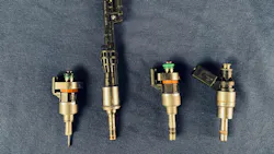
Injector deposits create a different problem. Direct injectors operate in a harsh environment. The tip is exposed to combustion heat and carbon blowback, and even a small amount of buildup can change the spray pattern. The injector may pass a resistance test and still not deliver fuel correctly. It may be electrically alive but mechanically compromised. A restricted or distorted spray pattern can create a lean cylinder, rough idle, positive fuel trim correction, P0300-type misfires, P219X air-fuel ratio (AFR) or cylinder fuel imbalance codes. A leaking injector can create the opposite concern, including rich operation, fuel dilution, hard starts, and rail pressure bleed-down.
Most OEM repair information doesn't treat a direct injector the same way we treated older port injectors. If the injector has an internal restriction, leakage, poor spray pattern, or cylinder imbalance concern, the factory repair is often a replacement, not cleaning. One newer development worth watching is the move toward even higher GDI injection pressure. Many earlier systems operated around 2,200 to 2,900 psi, but newer systems have moved into the 5,000-psi range, and 7,250-psi-plus systems are now being developed and entering production. The goal is better atomization, fewer large fuel droplets, cleaner combustion, and lower particulate emissions. From a diagnostic standpoint, this means pressure control, injector sealing, line integrity, and scope setup become even more important. As operating pressure goes up, the system becomes less forgiving of small leaks, incorrect service procedures, weak pump control, or poor injector performance.
Injector Balance Testing
Injector balance testing can be very useful on GDI systems, but the results only mean something when the test is run under the correct conditions. GM pickups are a good example. On a 2017 GMC Sierra 5.3L, the balance test must be performed with the engine coolant temperature below 140 degrees Fahrenheit. If the engine is hotter than that, fuel density and expansion change enough to skew the pressure-drop readings. At that point, the numbers may look useful, but the test is no longer valid.
On the 2017 system, each injector is pulsed for the same amount of time, and the pressure drop is compared cylinder-to-cylinder. The injectors should be within about 10% of the average. A lower pressure drop points toward a weak or restricted injector, while a higher pressure drop points toward a leaking or over-fueling injector. Even then, bank-to-bank differences have to be interpreted carefully because rail sensor location can influence how quickly the pressure change is seen.
The 2019 and newer GM 5.3L systems use a different procedure. The acceptable range is wider at 20%, and the setup is more controlled. The preferred method is the Active Fuel Injector Tester because it connects at the ECM harness and checks the high-pressure pump, injector wiring, and injector performance under controlled conditions. Before testing, the injector and ECM connector temperature must be stabilized between 66 and 70 degrees Fahrenheit. The scan tool test can still be used as a secondary method, but it's performed on a fully warmed-up engine at idle. The point is simple: don't compare results from different procedures as if they're the same test. With injector balance testing, the goal isn't to chase the largest pressure drop number. The goal is to compare injector-to-injector consistency under the correct test conditions. If the setup is wrong, the numbers are just noise.
Low-Side and High-Side Fuel Pressure
Low-side and high-side fuel pressure should always be separated early in the diagnostic process. The low side feeds the high-pressure pump. If the low side is unstable, restricted, aerated, or losing pressure under heat and load, the high side can't be judged accurately. A good scan tool gives us useful data here. Desired low-side pressure, actual low-side pressure, desired rail pressure, actual rail pressure, and pump command need to be looked at together. A throttle snap or loaded test can be very revealing. The high side should respond to demand, while the low side should remain stable enough to feed the high-pressure pump.
Ford Recall 25S75, NHTSA Campaign 25V455, is a good example of why the low side has to be checked first. The recall involves low-pressure fuel pump failure on certain 2021–2023 Ford and Lincoln vehicles. A loss of pressure or flow from the fuel delivery module can cause rough running, misfire-like symptoms, reduced power, a check engine light, no-start, or stalling. Those symptoms can look like a GDI injector or high-pressure pump problem, but the root cause may still be the pump in the tank. Before condemning the high-pressure side, the low-side supply has to be verified.
Once the low-side pressure and supply is verified, then the high-pressure system can be evaluated. The high-pressure pump is mechanically driven but electrically controlled. That means a pressure fault can be mechanical, electrical, or hydraulic. The PCM may be commanding the pump correctly, but the pump may not be able to build pressure. Or the pump may be capable of building pressure, but the control solenoid, wiring, PCM driver, or pressure sensor may be misleading the system. Desired pressure and actual pressure should always be close, and pump command status and solenoid current need to line up as well.
High-pressure pump testing should not focus only on low-pressure faults. The Kia 3.3L GDI P0088 (Fuel Rail-System Pressure Too High) issue is a good reminder of that. In this case, the fuel control valve plunger in the high-pressure pump can wear unevenly and stick open, causing rail pressure to go higher than commanded. The symptoms can include rough running, hesitation, MIL illumination, and a fuel rail pressure too high code. If the pressure is too high, the diagnostic path has to include the control valve and the pump's ability to regulate pressure, not just its ability to produce pressure.
Scope Testing
Scope testing is where GDI diagnostics really become clear. A voltage trace tells you what the PCM supplied. A current ramp tells you what the circuit consumed. Both matter. A GDI injector will use a boosted supply voltage, often around 65 volts or higher, to open the injector quickly against cylinder pressure. The current pattern then transitions from a high opening current to a lower hold current.
Scope setup is critical when testing GDI injectors. Because these circuits use boosted voltage, an attenuator must be used to protect the scope. The time base, voltage scale, current scale, sample rate, and filtering all must be set properly before the pattern is judged. If the setup is wrong, a good injector signal can be distorted and appear faulty, leading the diagnosis in the wrong direction.
Injector access is another place where GDI diagnostics have changed. On older port fuel injection systems, it was common to have one fused power feed supplying all of the injectors, with the PCM controlling the ground side. Access was usually simple, and checking injector power or control didn't require much disassembly. On many GDI systems, that's no longer the case. The injectors are powered and controlled directly through the PCM, and the injector harness may be buried under the intake or sealed in a way that makes direct backprobing a poor first choice.
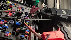
These access limitations don't mean the system is difficult to test. On many GDI systems, the injector current is supplied through the PCM, and the PCM receives that power through several fused feeds in the fuse block. The wiring diagram will show the PCM power feeds, but it won't always identify which fuse is carrying the injector current. In most cases, the larger ignition-controlled PCM feeds are the best place to start.
A simple way to test this is to install a fused jumper assembly in place of one PCM ignition feed at a time and clamp a low-amp current probe around the jumper wire. This allows the technician to indirectly view injector current activity on the scope without backprobing the PCM connector or disturbing the injector harness. Work through the PCM ignition feeds until the injector current events are found.
Once the correct feed is identified, the scope can show whether the injector events are present, evenly spaced, and synchronized. Adding a coil sync or another timing reference allows the injector events to be lined up with crankshaft position and firing order. This doesn't replace direct injector voltage testing when a circuit fault has to be isolated, but it's an excellent first test because it confirms injector activity quickly, safely, and with very little disassembly.
High-Pressure Pump Service
High-pressure pump service is an area where comebacks can be created. These pumps are driven by a cam lobe, follower, or pump drive arrangement, and installation position matters. If the pump is tightened while loaded against the high point of the cam, the pump can be damaged or distorted. Some systems require alignment tools, specific crankshaft position, new bolts, new seals, and new high-pressure lines when providing service or replacement.
The Ford Bronco and Ranger high-pressure pump mounting bolt recall (Ford Recall 25S90 and NHTSA Campaign 25V597) is a good reminder that GDI pump installation is precision work. In this case, the concern involved HPFP mounting bolts that could fail and allow pump movement. The result could be low fuel pressure, noise, oil leakage, reduced performance, or fuel line fatigue. It's a small recall, but it makes the point clearly: bolt torque, pump position, line replacement, and the proper service procedure all matter.
High-pressure lines and seals also need respect. Many of these lines use sealing surfaces that deform when torqued. Once loosened, they shouldn't be reused unless the service information specifically allows it. The same applies to injector seals, Teflon combustion seals, hold-down hardware, pump gaskets, and some pressure sensors. A reused line may not leak in the bay, but it can leak later under heat, vibration, and pressure. That can create fuel smell, pressure loss, misfire, or a safety issue.
Engine Oil and Maintenance
Engine oil and maintenance also affect GDI more than many customers understand. The GDI high-pressure pump rides on a mechanical drive surface, and some engines use followers that are very sensitive to wear. Poor oil maintenance can affect the follower, cam lobe, pump drive, and variable valve timing system. Ring deposits and blow-by also contribute to oil vapor entering the intake. That vapor can build deposits on the throttle body, intake runners, valves, piston crowns, and ring lands. On a GDI engine, a fuel system complaint may actually have an oil control or mechanical sealing component behind it.
Cold-start catalyst heating can also confuse GDI diagnosis if the technician isn't expecting it. On many GDI engines, the PCM will use split injection and late ignition timing for a short period after start-up to get heat into the catalyst quickly. One injection event may occur early in the intake stroke, while a second event may occur later in the compression stroke to keep the mixture stable near the spark plug. On the scope, this will show up as multiple injector events instead of one clean pulse per cycle. This shouldn't be mistaken for an injector fault. Once the catalyst heating strategy ends, the pattern should return to a normal warm-idle injection event. Some systems also change the misfire monitoring window during this time because combustion is being delayed on purpose.
Low-Side Pump Evolution
Modern low-side pumps are changing too. Many newer systems use three-phase brushless pumps controlled by a fuel pump driver module. These aren't old-style two-wire pumps where one wire is power and one wire is ground in a simple sense. The module creates phased control signals, and the pump speed changes based on demand. A voltmeter check may not tell the story. A scope pattern across the phases and a current ramp during bidirectional control will show whether the module, wiring, and pump are responding correctly.
The Bottom Line
GDI systems have made gasoline engines cleaner, stronger, and more efficient, but they've also made diagnostics less forgiving. The engine still needs the same basics it always has: air, fuel, spark, compression, and proper timing. The difference is that each one of those areas now has more layers to test.
A GDI fault shouldn't be called from one code, one pressure reading, or one scope pattern. Low-side supply, high-side pressure control, injector command, injector delivery, ignition, airflow, and mechanical condition all have to support the final diagnosis. When those pieces line up, the repair is no longer a guess. It's proven before the vehicle leaves the bay.