In the quest for better fuel mileage and emission production from the internal combustion engine, new technologies have emerged. One such technology is Displacement on Demand (DoD), also referred to as Variable Engine Displacement. DoD is a system that extracts more thermal efficiency from the fuel stock used by the internal combustion engine. This is accomplished by the deactivation of cylinders within the engine.
The birth of DoD
Multi-cylinder engines that produce high power are commonly used in modern vehicles. These types of engines are necessary to provide rapid acceleration and/or towing capacity for the vehicle. The problem is that these high engine power demands are only used by the driver for a small percentage of the vehicle’s overall life. For example, a vehicle at highway speed will require less than 40 horsepower to overcome the parasitic losses. These losses occur from such things as aerodynamic drag, rolling friction, and accessories such as air conditioning, alternator, power steering, etc.
Currently, most DoD systems are used on large displacement gasoline-style engines. On these large, displaced engines, the throttle plate position is less than 40 percent for most of the vehicle’s driving time. This means that under light load, the effective compression ratio is lower than the effective compression ratio under heavy load. This decrease of the effective compression ratio under light engine load conditions decreases the thermodynamic efficiency of the engine. Under light load, the cylinder fill volume is far less than 100 percent. This is due to the throttle plate and the airflow velocity moving through the engine.
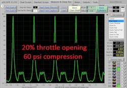
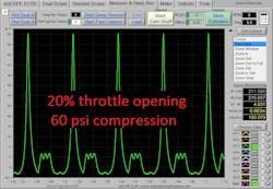
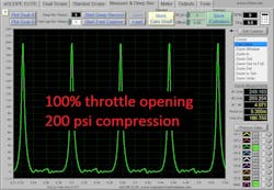
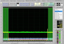
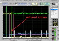
With less volume fill within the cylinder, the compression pressure is much lower than the static compression set point. Under heavy engine load, where the throttle plate is at WOT, the volume contained within the cylinder is high so the static compression ratio pressure can be more closely obtained. This throttle plate effect is shown in Figures 1 and 2. This is a Chevrolet 5.3L V8 DoD engine with a pressure transducer within the cylinder.
The spark is not present within the cylinder, so the fuel stock did not ignite and burn. This is the compression and decompression that occurs within the cylinder as the throttle plate angle is changed from 20 percent to 100 percent.
As can be seen in Figure 1, at light load the peak pressures are about 60 psi, and in Figure 2 the peak pressures at heavy load are about 200 psi. With greater cylinder pressure there is greater cylinder temperature as well. The thermodynamic laws that apply to all heat engines dictate that the engine will then be operating at less than its maximum possible thermal efficiency. The engine’s thermodynamic efficiency is a measure of how effectively the engine converts heat into mechanical power.
To understand how this occurs, it is necessary to look at the engine’s expansion ratio. The expansion ratio explains what occurs as the piston is moving downward while the fuel is burning, creating pressure within the combustion chamber. Since the air volume within the combustion chamber is changing as the engine is throttled, the peak pressure is also changing within the cylinder. The higher the peak compression pressure within the cylinder, the greater the pressure and temperature will be as the piston descends the cylinder.
As the fuel releases its thermal energy it heats the working fluid (nitrogen), which then creates pressure within the combustion chamber. The pressure is the force multiplied by the area. Pressure per Square Inch (PSI) or, more accurately, pound-force per square inch is the force of one pound-force applied to an area of one square inch, so the pressure within the combustion chamber is multiplied by the area of the piston, thus the higher the cylinder pressure, the more force is created to push down on the piston.
This would indicate that an engine is less efficient during normal light load driving conditions; less air volume equals less pressure and heat, yet far more efficient during heavy load driving conditions, more air volume equals greater pressure and heat.
In a typical light load driving condition the driver only uses about 30 percent of the engine’s total power capacity. This would indicate that the throttle plate is nearly closed. In these conditions, the engine’s intake manifold vacuum is high, so the engine will work harder to pull air into the cylinder. This parasitic pumping loss of the engine’s efficiency is referred to as suctioning throttle loss. Large multi-cylinder displacement engines will need to be throttled so much so at light cruise that the effective pressure at TDC is half that of a small displacement 4-cylinder engine in the same operating conditions. As we have seen in the internal combustion engine, low cylinder pressures result in low fuel efficiency.
Extracting the efficiency by eliminating loads
Once this simple fact is realized, the question would be how can the possible thermal efficiency be increased during these light load conditions? There are many ways that the cylinder charge rate can be increased during light load conditions, but perhaps the best way to accomplish this is with cylinder deactivation.
Cylinder deactivation is the process where several cylinders within the engine structure are deactivated by not opening the valves in those particular cylinders, effectively spreading the workload of the engine over fewer active cylinders. This will increase the cylinder fill rates of each of the active cylinders, thus increasing the thermal efficiency of the engine. Additionally, there is a friction-based gain by deactivating the cylinders as well.
Losses due to the friction between the piston, piston rings, and the cylinder bore are a function of both sliding velocity and normal load. The sliding velocity friction loss is a product of the rotation speed of the engine and therefore unchanged by cylinder deactivation. However, when the fuel is ignited and burned there is a side load placed on the piston, piston rings, and cylinder bore. If the fuel is not ignited within the cylinder this sideload is decreased, which in turn will decrease the friction losses of the engine making it more efficient.
When the cylinders of an engine are deactivated there are fewer cylinders pulling air from the intake manifold resulting in less vacuum within the induction system. Additionally, the throttle plate is opened slightly to allow more air into the fewer active cylinders within the engine. This works to reduce the suction throttling losses of the engine, as illustrated in Figure 3.
Additionally, the cylinder air volume increases in each of the active cylinders, which increases the pressure and heat within the cylinder. These events—reductions in pumping losses and higher cylinder pressure—is what the DoD system is striving to accomplish, so what would the actual gain of a variable displacement engine be? Fuel consumption can be reduced by as much as six percent to 25 percent under light load conditions? In real world conditions, one could expect approximately six percent to 12 percent fuel consumption gains. For example, if an 8-cylinder engine is operated at light load, then all eight cylinders are having fuel delivered to them.
However, the power needed to move the vehicle would not require the maximum power produced from the displacement of the entire engine. Therefore, if half of the cylinders within the engine are deactivated, then only half of the cylinders are fueled. This in turn will reduce the fuel delivered to the engine.
It’s a game of give and take
Cylinder deactivation is accomplished by keeping the intake and exhaust valves closed during light engine load conditions. This closing of the valves creates an air spring effect within the cylinder. The microprocessor in the Engine Control Module (ECM) monitors what stroke the engine is on.
One method of DoD implementation is to close the valve at the end of the exhaust stroke near the TDC position. This allows for an atmospheric charge to be present within the cylinder. Another method is to not open the valves after the power stroke has occurred; this traps the exhaust gases in the cylinder.
With either method, these gases are then compressed during the compression stroke and decompressed during the power stroke, so the energy used during the compression stroke is returned to the engine during the decompression stroke, thus the compression and decompression of the trapped gases have an equalizing effect. This compression-decompression cycle is repeated until the DoD system is deactivated.
For example, if more engine power is needed, the exhaust valve is reopened allowing the exhaust gases to be pushed from the engine. The intake valve is reopened, allowing an air charge to be pulled into the cylinder. The engine is now running under normal operating conditions. The transition between normal engine operation and cylinder deactivation is smoothed using changes in ignition timing, cam timing, and throttle position.
Generally, four critical conditions will need to be met for the ECM to deactivate cylinders within the engine. These conditions are:
- The water temperature greater than 180 degrees
- The transmission in 3rd or higher gear
- The intake manifold vacuum above 9 inches of HG
- The vehicle speed above 45 mph
Remember that all of these enabling criteria must be met to deactivate the cylinders within the engine. In testing, one manufacturer showed that the DoD system on a V8 was activated in suburban driving 17 percent of the time, achieving a 7.7 percent increase in fuel efficiency; in highway driving 48 percent of the time, achieving a 17 percent increase in fuel efficiency, and on average, the engine powered down to four cylinders 40 percent of the time.
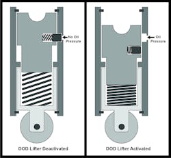
There are several methods in which the cylinders within the engine can be deactivated. We will only cover one of these cylinder deactivation systems in this article. This is a pushrod style lifter that can be deactivated and is referred to as a lost motion lifter. As can be seen in Figure 4 , several components are comprising this style lifter.
The inner pushrod assembly is pinned to the outer lifter housing. As long as the locking pin is locked to the outer lifter housing, the lifter will work to convey the mechanical movement of the camshaft to the valve assembly. This locked position is the default for this style lifter.
When the DoD microprocessor determines that the cylinders need to be deactivated, the lifter is activated by dislodging the locking pin. This is accomplished with the use of hydraulic pressure created by the engine oil pressure system. When engine oil pressure is supplied to the locking pin, the locking pin is pushed back against the mechanical spring pressure unlocking the lifter, as seen in Figure 4. This in turn allows the lifter to collapse within itself, which closes the valve.
The spring located beneath the inner push rod assembly prevents the pushrod from moving while allowing the lifter roller to follow the camshaft lobe. Once the oil pressure is shut off, the locking pin will be forced back into the lifter body by the mechanical spring pressure, thus returning the mechanical movement of the camshaft to the valve assembly.
The engine oil pressure is controlled with an oil pressure control solenoid. This solenoid is a naturally closed device, thus shutting off the oil pressure to the DoD lifter. To activate the solenoid, the ECM turns on a transistor, which grounds the circuit. This DoD control circuit activation is shown here in a lab scope capture (Figures 5 and 6):
- YELLOW = DoD solenoid control circuit
- GREEN = Fuel injector control circuit
- WHITE = Ignition coil command control circuit partitioned with 720-degree overlay
- BLUE = MAP sensor input signal circuit
- PURPLE = TPS sensor input signal circuit
With the yellow trace falling from source voltage to ground is when this transistor is turned on. As can be seen, the fuel injector is shut off just before cylinder deactivation occurs and is not turned on again until the cylinder is reactivated again. This cylinder is deactivated before the TDC position on the exhaust stroke, which allows the cylinder pressure to be at a neutral atmospheric pressure, as seen in Figure 6.
This is shown at the pink index lines indicating the four engine strokes: power, exhaust, intake, and compression. Note these pink marks are between the ignition events on this cylinder shown in white or 720 degrees (which is two complete crankshaft revolutions and equals one complete engine cycle). The injector is activated during the exhaust event before the piston reaches the TDC position. Then the cylinder is deactivated, closing the intake valves and exhaust valves. The valves will remain closed until the cylinder is reactivated by deactivating the lifters.
Additionally, in Figure 6 during the cylinder’s deactivation (shown by the falling yellow trace), the intake manifold pressure increases towards the atmosphere, shown by the blue trace. The TPS is also slightly increased to allow more air into the engine, as shown by the purple trace. The cylinder is reactivated just before the exhaust TDC position, as shown in Figure 5. The fuel that was injected just before deactivating the cylinder is now pulled into the cylinder where it is ignited and burned, thus restoring normal engine operation.
Every action has a reaction
Due to the difference in the vibration and acoustic dynamics of the engine being run under cylinder deactivation and running the engine with the cylinders fully activated, the intake and exhaust will need to be tuned to compensate for the changes in flow dynamics. Additionally, half of the cylinders of the engine will be deactivated to limit vibration from the engine. This will allow for an even firing of the engine.
For a V8, when you deactivate four cylinders you increase the rotation between firing from 90 degrees to 180 degrees. For a V6, when you deactivate three of the cylinders, you increase the rotation between firing from 120 degrees to 240 degrees. The problem is that the frequency of harmonic vibrations has now increased, and the natural dampening has decreased.
For example, on a Dodge 5.7 Liter DoD engine, the firing order is 1-8-4-3-6-5-7-2; the cylinders that are deactivated are 1-4-6-7. These cylinders are the two end cylinders on bank one and the two inner cylinders on bank two.
On our example engine, which is a Chevrolet 5.3 Liter DoD engine, the firing order is 1-8-7-2-6-5-4-3; the cylinders that are deactivated are 1-2-4-3. These are the front two cylinders on bank one, and the front two cylinders on bank two, so the firing order scheme will be important to keep the engine running smoothly during cylinder deactivation.
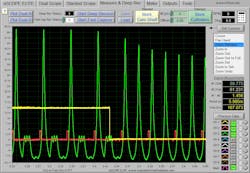
The in-cylinder pressure is shown during cylinder deactivation (Figure 7) :
- YELLOW = DoD solenoid control circuit
- GREEN = In-cylinder pressure changes
- RED = Ignition coil command circuit
As can be seen, when the DoD solenoid is commanded on the DoD lifters are activated, closing the intake and exhaust valve. This in turn changes the in-cylinder pressure after the source voltage is pulled to the ground (indicated by the falling of the yellow trace). Before the yellow trace fell the pressure was only built every other crankshaft revolution (NOTE: The red trace indicates the ignition firing events that are commanded every other crankshaft revolution)
Once the yellow trace falls the in-cylinder pressure builds every crankshaft revolution. This is due to the valves not opening, allowing the in-cylinder pressure to change. Thus, every time the cylinder comes up on a TDC position pressure is produced. Each time the piston descends in the cylinder bore the pressure decreases. This compression-decompression air spring effect of the in-cylinder gases neutralizes the cylinder efficiency losses during cylinder deactivation.
There are many names that the different manufactures will use when referring to these DoD systems. However, the basic ideas will remain the same. The actual implementation of how the valve closing and opening will operate will differ but with a basic understanding of how these systems work, and a little study on the different systems, you will be able to quickly and accurately diagnose this system in your service bays.
About the Author
Bernie Thompson
Contributing Editor
Bernie Thompson is an accomplished automotive diagnostician and trainer, and is also the co-founder of Automotive Test Solutions (ATS) based in Albuquerque, New Mexico. He has over 40 years of experience in automotive gasoline and diesel repair. Over twenty years of experience in design, engineering, and fabrication of automotive diagnostic equipment. Mr. Thompson holds; 22 US patents, 1 European patent, 1 Canadian patent, with 22 U.S. patents pending, 3 European patents pending, and 3 Canadian patents pending. Additionally Mr. Thompson writes automotive training curriculum for the automotive industry, is an editorial contributor for Motor Magazine, Motor Age Magazine, and has co-authored an SAE paper. Thompson also teaches advanced automotive diagnostic curriculum internationally. Connect with Thompson on the ATS Facebook page.
