Testing the ECM: Read this before you order a replacement
Content brought to you by Motor Age. To subscribe click here.
What you will learn:
• Scan data can be too slow to capture a glitch; the scope can reveal the fault
• Often software malfunctions are corrected through re-programming. TSBs can alert us to these updates
• The "20/20" rule can help you with initial scope set up
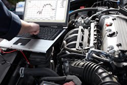
Ever use an OEM flow chart as part of your driveability diagnostic process? I’m betting you have. And when the next step tells you to replace the engine control module, there is always some hesitation, isn’t there? After all, a new ECM can cost a lot of money and you want to be sure that replacing it is going to resolve your customer’s concern.
What does the ECM do, and how does it do it?
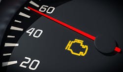
The engine control module (ECM) is the computer that manages every system on the vehicle related to emissions. When something goes wrong, the ECM will hopefully record a diagnostic trouble code and turn on the check engine light. But the ECM (all by itself) can do nothing. It first must be programmed. These are the instructions the engineers have given it so it can perform its primary function — maintain the vehicle’s emissions levels.
Granted, there are several subsystems involved (like the ignition system, the fuel delivery system, the EVAP system, and others). But generically, the process the ECM follows is the same. First, it has to have the information it needs to carry out its programming. This information is supplied by a variety of sensors like the crank and cam sensors (for engine position), the MAF sensor (for the amount of air being taken in), and the various temperature sensors associated with the engine.
Once the ECM has the information it needs, it plugs that data into the parameters programmed into it and then carries out the tasks associated with those parameters. This is typically done by controlling the operation of numerous circuits (using low- or high-side drivers). Drivers are nothing more than a switch the ECM turns on or off. Low-side drivers complete the ground path of the circuit it is connected to while high-side drivers supply a power source to the circuit it operates.
In many cases, there is also some kind of feedback strategy involved to let the computer know that the action it took was carried out. Oxygen sensors are an example of a sensor that provides direct feedback to the ECM. In other instances, the ECM looks for certain changes in other monitored systems as feedback. Granted, this is a bit simplistic. The idea I want you to take from this is that there are several things we need to confirm before we blame the ECM.
Is the ECM getting the information it needs?
We have to make sure the ECM is getting the information it needs from its sensors. We also have to verify that the sensors are reporting accurately. The ECM can only act on the data its receiving and may not know that it's being lied to!
One way to see if the data is making its way to the ECM is to look at the data PIDs using your scan tool. We can get an idea of the accuracy of the information by changing the engine’s state and seeing if the data PID changes in response, or by comparing the data to another sensor to see if the two are in alignment.
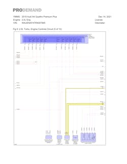
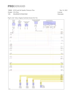
Here’s an example. The RPM PID is a direct input from the CKP (crankshaft position sensor). With the engine warm and idling, is this reading normal or abnormal? Now, open and close the throttle. You should see the data PID change in response. Sometimes misinformation fed to the ECM occurs intermittently, and at speeds that may be too fast for your scan tool. That’s where the MS919’s scope comes in. Let’s connect to the CKP and see what the scope can tell us. Connect the scope by first looking at the engine performance wiring diagram. Identify the wires leading to the CKP sensor. This engine uses a 3-wire crank sensor (one voltage supply, one ground, and one signal wire back to the ECM). I’ll connect one channel to the signal wire at the ECM.
Next, we need to set up our scope to capture this signal. I use the 20/20 rule to start. The 20/20 rule means that I need to set my voltage scale to cover a 20V range (appropriate since most of the vehicle systems are 12V systems). The second 20 means that I need to set the time scale to 20ms per division. That gives me a total time on the screen of two seconds (about the amount of time it takes for the engine to complete two full revolutions). Last, I need a trigger. Let’s use Autel’s “automatic” option and see what we get.
Finally, we’ll start the engine and capture the signal pattern. You can adjust the scope’s voltage and time scales to get a better pattern. The pattern should be clean and repetitive, with no dropouts. Signals also have to reach minimum levels for the ECM to see and recognize them, so it helps to compare your capture to a “known good”.
If you suspect an intermittent signal loss, you can try the “picket fence” technique. This is where you adjust the time scales to a higher value until the pattern looks like a smear but still somewhat distinguishable. Now if a dropout occurs, you’ll see it as a missing picket in your picket fence!
Sensor signals to the ECM will vary depending on the type of sensor. Some will be a digital signal like this one, others will be a AC signal similar to an AC sine wave, and others will be a varying voltage like the one produced by a throttle position sensor. No matter what kind of signal, it must be clean with no drops for the ECM to make use of it.
Are the ECM's instructions flawed?
When the ECM has the information it needs, it will fall back to its programming to decide on the action it needs to take. On occasion, issues with the systems controlled by the ECM are a result of mistakes in the programming itself. This is why it is so important to consult the factory Technical Service Bulletins (TSB) early on in your diagnostic process. If a change in programming was made, it's likely the only way you’ll find out about it.
Reprogramming the ECM with updated software is the fix and the Autel VCI I’m using is also a J-2534 interface that I can use to do just that in many cases. If you find yourself in a situation where the vehicle you’re working on requires reprogramming be sure to do your homework and get additional training in order to perform this procedure correctly. Mistakes made here can result in your killing an otherwise healthy ECM.
Can the ECM carry out its instructions?
If the programming is correct, the ECM will then carry out the actions specified. As I mentioned earlier, this is done by controlling the electrical components associated with the needed action by opening and closing the circuit via internal drivers — or switches. This is a common area for ECMs to fail. As with any other electrical device, the drivers can become damaged and inoperative, and the actions may be commanded by the ECM but not carried out. So, the next step in our diagnosis is to verify that the ECM is commanding the action and that the controlled component is working like it’s supposed to.
In many instances, you can simply use the bidirectional controls of the scan tool to operate the device. If the PID associated with the device changes state but the component isn’t doing anything, troubleshoot the circuit as you would any other. In the cases where bidirectional control isn’t possible, you can use your scope instead. Let’s use the fuel injectors on this Audi as an example. This engine uses GDI (gasoline direct injection), with two wires going to each injector. Again, we start by reviewing the wiring diagram.
The operation of the GDI electro-mechanical injectors is a bit different than conventional port fuel injection units. These injectors require initial voltages of 65v to open, and this voltage is supplied by the ECM. The ECM also controls the ground side of the injector circuit. We can look at the scan tool data and get an idea of the time the ECM is commanding the injectors on, but we may not be able to see each individually. We also can't tell if the injector did indeed respond to the ECM's command. We can, though, with a scope.
We start with our 20/20 rule to set up our initial voltage and time divisions. Next, I’ll connect one channel on the Autel scope to one of the injector grounds. I’ll also connect one channel to the positive side of the injector connector.
A word of caution here — many of the devices the ECM controls use a coil of wire that builds a magnetic field when current is passed through it. The magnetic field is what is used to perform the work (energize a secondary ignition coil, open an injector or solenoid — these are some examples). This collapse also produces what is called a “flyback” voltage (on the ground side of the circuit) that can reach levels unsafe for your scope unless an accessory called an attenuator is used to drop the voltage to a more friendly level. Make sure you know the maximum input of your scope to avoid damage to it.
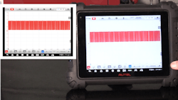
I’ll then add a new measurement tool to a third channel, the low amp probe (to monitor the current flow on the feed wire to the injectors). With the scope connected, let’s start the engine and capture our pattern.
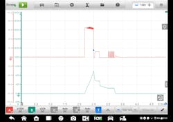
I like to look at the current capture first. What if the current on any of the injectors is lower than the others? That could indicate a resistance issue in the circuit itself (a bad ground, corroded connection, or something similar). What do you think can happen if an injector or other actuator shorts internally? Resistance will be less than specified and that means the current flow in the circuit will be higher than it should be. We’ll see that in the current pattern too. This is a common cause of driver damage in the ECM and I’m going to talk more about that in a moment.
If the component is not working as it should, we need to apply our electrical troubleshooting skills to determine where the circuit fault lies. Many times, it isn't the fault of the ECM, but a problem with voltage drop somewhere in the circuit path. Pin/connector damage is very common and can be caused by corrosion, water intrusion, improper handling of the connector or improper testing methods (like shoving a test probe into a hole too small for the probe).
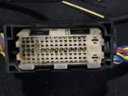
Disconnect the connector from the ECM following the OE service procedure. Use your phone’s camera to take a picture of the connector and the connecting pins on the module; this makes it easy to blow it up and get a real close view. Look for signs of corrosion or damage. You can use electrical contact cleaner or pure rubbing alcohol to clean them up and I like to use a product called Stabilant 22 as a final touch.
Stabilant 22 is an initially non-conductive block polymer that, when used in a thin film, switches to a conductive state under the effect of the electrical field. It remains nonconductive between adjacent contacts when applied to electromechanical contacts, Stabilant 22 provides the connection reliability of a soldered joint without bonding the contacting surfaces together.
Once you've determined that every other part of the circuit is correct, then — and only then — consider the possibility that the ECM circuits are damaged. Before you order that new one, though, you need to identify why it failed!
If the ECM is bad, what caused it to fail?
Measure the resistance on the injector and compare to specification. If it’s low, odds are the excess current caused by the shorted injector is the reason for the failure. You should also verify the resistance on every actuator circuit operated by the ECM to ensure none of them had anything to do with it. And, of course, use the voltage drop testing method to verify the module’s power and ground circuits.
Remember, the ECM is the most expensive fuse on the car! Take the time to determine the root cause of the concern and, if you do determine that the ECM has failed, be sure you check all the possibilities for its failure before replacement.
About the Author

Pete Meier
Dorman Training Center Instructor and Former Creative Director, Technical | Vehicle Repair Group
Pete Meier is the former creative director, technical, for the Vehicle Repair Group with Endeavor Business Media. He is an ASE certified Master Technician with over 35 years of practical experience as a technician and educator, covering a wide variety of makes and models. He began writing for Motor Age as a contributor in 2006 and joined the magazine full-time as technical editor in 2010. Pete grew the Motor Age YouTube channel to more than 100,000 subscribers by delivering essential training videos for technicians at all levels.
Connect with Pete on LinkedIn.