Technical Reference: Throttle Motor control systems

There are many systems and functions in the modern motor vehicle which require a method of controlling and reversing the electrical polarity of a circuit. The most common process is controlling the direction of rotation of a motor, specifically the electric window motor, electric power steering motor, electronic throttle control motor, etc.
Electronic throttle control
Electronic throttle control has now become standard fitment in all spark ignition engines. This has allowed for advancements in technology such as cruise control, traction control, limited operating strategy (limp home mode), and engine speed limiter. Although these functions previously existed, electronic throttle control has further refined the operation of the vehicle, complementing these functions.
Another advantage of electronic throttle control has been seen on vehicles with direct fuel injection, which can function in two modes, homogeneous and stratified. Homogeneous mode is when the engine runs on a stoichiometric air to fuel ratio of 14.7:1, and fuel is injected late on the exhaust stroke/early on the intake stroke. The fuel and air mix to give a homogenous fuel mixture.
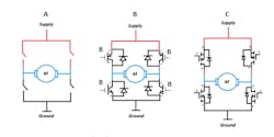
Stratified mode is when fuel is injected late on the compression stroke, and the mixture formation is heterogeneous. See the diagram below:

On the diagram, the blue circles represent air, and the red circles represent fuel. As can be seen, the mixture is exceptionally rich in the center of the heterogeneous mixture, but overall as a whole, the mixture is lean. Under stratified running mode, the throttle valve is held fully open, and the driver demand (accelerator pedal input) is varied by adjusting the quantity and pressure of the fuel being delivered. Without electronic throttle control, this functionality would be at best complex, or more realistically, would be impossible, as there has to be a complete disconnect between the accelerator pedal input and the control of the throttle valve.
Vehicles fitted with electronic control can precisely control idle speed and also use additional processes, such as closing the throttle valve slightly under cranking to improve engine start-up. This is controlled by changing the electrical polarity of the throttle motor. The image below shows a basic electronic throttle control system:

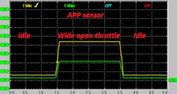
As can be seen from the image, accurate monitoring of the accelerator pedal position (APP) and throttle motor position (TPMS) are required. These sensors have two/three outputs for redundancy and fault detection. In the case of a single track/circuit failure, the system can still function, as well as electrical short and open circuits can easily be detected. Below is an example of both APP and TPMS position sensor waveforms:

Motor control
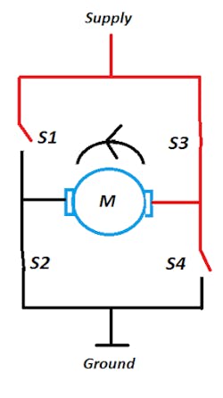
As previously outlined, the polarity of the motor is reversible, which allows accurate control of the entire system. A way to control the polarity is by designing a circuit referred to as an “H-drive” bridge circuit. The bridge circuit can be created using IGBT (insulated gate bipolar junction transistors) or MOSFETS (metal oxide field effect transistors). The latter being the most common way of controlling such a circuit. A control circuit using mechanical switches is shown for demonstration purposes.
Below are two images which demonstrate the fundamental operation of the circuit. Basic mechanical switches are used to simplify the circuit:

Feedback and control
As previously outlined, the engine control module uses the feedback from the accelerator pedal position sensor to determine driver demand. Vehicle demands may also exist in the form of a traction control system command or from the engine speed limiter. However, for correct operation of the electronic throttle control motor, a closed loop control system must be implemented using throttle position sensors.
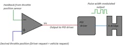
In this simplified example, an operational amplifier voltage comparator uses inputs from both the desired throttle position and actual throttle position. The output (Vo) from the comparator is the voltage difference between both signal voltages applied. This output voltage is used to control a PID (proportional, integral, derivative) driver, which then outputs a PWM (pulse width modulated) control to the H drive circuit.
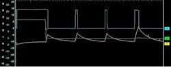
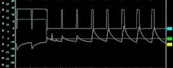
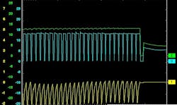
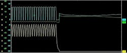
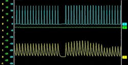
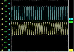
Current flow and voltage waveform analysis
Below are oscilloscope waveforms captured from a vehicle. The yellow trace is the current flow through the motor, and both the green and blue traces are the motor voltage control wires with a hard ground as the reference for the oscilloscope.
About the Author

Damien Coleman
Damien Coleman started as an apprentice in 1999 at a GM dealership. In 2003 he competed in the final of the national skills competition. He completed his diploma in advanced automobile engineering and automobile electricity in 2004. In 2006 Coleman joined and started his career at Snap-on. In his spare time he has lectured at the Cork Institute of Technology, teaching automotive diagnostics.