
I think this month’s case study will have HD techs very interested. As everyone knows Diesel Exhaust Fluid (DEF) Pumps are now in use on every aftertreatment system out there today on the modern heavy-duty vehicle. They are used to supply pressurized fluid to the doser injector, so it can deliver the fluid in an atomized spray into the selective catalyst reduction (SCR) chamber. Within the chamber, a chemical reaction takes place, and the result is a reduction in oxides of nitrogen (NOx). We understand the theory of how the pump is supposed to work, but how do we diagnose a DEF pump problem?
In this article, I am going to show you how to diagnose a faulty DEF pump with a scope. This method is much faster than doing all the resistance checks the manufacturer wants you to do on the harness, according to service information.
These DEF pumps are not your average DC electric motors anymore (ones containing brushes/commutator that are energized through a switch). These electronic-controlled pumps need digital signals to work. Depending on the model, some will have a pressure sensor built internally to monitor pressure and will have valves in the pump to redirect flow during a purge cycle.
The other design I have seen (which seems to be common in many aftertreatment systems) is one having a pump without check valves. In this design, when the system shuts down, the DEF just goes back to the tank by gravity and depressurizes over time, but every DEF pump I have seen recently indeed has a brushless DC motor.
These brushless motors work by having north and south pole magnets mounted on a circular rotating assembly that attaches to the mechanical shaft of the pump. These magnets pass near field coils. When a set of coils is energized with current, the magnetic field of the coils causes the magnets to attract and then repel, which then give mechanical motion to the shaft of the rotor.
The field coil current is controlled by a microprocessor inside the pump, which controls when each coil is energized, so in order to know RPM of these types of brushless pumps, you have to know how many field coils they have. Also, on other systems, including the one I am going to talk about, there is a pressure sensor built into the doser.
My advice to everyone here is to make sure you look at service information and understand the system before you formulate a test plan. Unfortunately, from what I have seen from different manufacturers, their troubleshooting information on these pumps is certainly lacking. Don’t get me wrong: most of the time you can fix these issues with the available information. However, the challenge is understanding how to efficiently fix a problem like this if they don't tell us how the system works, or the signals the system relies on to function. Many times I like to figure out how systems work with a scope, so I may become more efficient in my diagnostic process.
The patient
We had a 2017 New Flyer 40 ft. Excelsior Low-Floor Bus with a B6.7 Cummins Engine. It has two DTCs
- 5865 — Diesel Exhaust Fluid Pump Command Circuit-Voltage Below Normal or Shorted to Low Source
- 5867 — Aftertreatment Diesel Exhaust Fluid Dosing Unit Relay Feedback-Voltage Below Normal or shorted to low Source
Next, I got an electrical schematic that I used with permission from diesel laptops, a diagnostic tool vendor that specializes in the sale of HD diagnostic tools and service information, as well as diesel technician training. There is a voltage, ground, control signal and a speed sensor signal to the pump. The Cummins ECM also gets a feedback voltage signal from the DEF dosing unit relay. This voltage signal (of 24V) on this model goes to the DEF pump and the Cummins ECM, which determines if the relay has turned on. This is one of the inputs the ECM uses to turn on the pump.

The DEF pump is tied into the same wire. Besides the pump needing voltage and ground, there are three other vital inputs that are involved:
- Command signal
- Speed sensor signal
- Pressure sensor signal
The pressure sensor is inside the doser injector on this model. The command signal is created by the Cummins ECM. It provides the path to ground for a 20V signal from the DEF pump for a calculated duty cycle. This is used to keep pressure built up in the system. The computer then looks at the speed of the pump and the pressure to determine if the pump is functioning properly.
It does this by increasing the on-time (signal pulled low) of the command signal to increase the current to the pump (Figure 1). This then increases the speed and pressure output of the pump. When the computer notices that the pump is at optimal pressure (from the pressure sensor signal in the doser, which is 127 to 130 psi), and it gets the correct speed signal feedback for that pressure, the computer then decreases the on-time of the command signal because the pressure has been achieved in the system.
The speed sensor operates at 4.6 to 4.8V, and this signal is pulled to ground by the pump. To indicate the speed to the computer, please refer to Figure 1 again. I have also taken this pump apart to determine how many field coils it has, and on this model year with the B6.7, the pump has 12 field coils and is a diaphragm-type pump.
You will see in the images captured two voltage transitions of the speed sensor signal. This indicates one full revolution of the pump (Figure 2). We can now measure this frequency and multiply it by 60 to get a RPM reading. Frequency is measured in Hertz (Hz), which reflects cycles per second (why I multiplied by 60 — there are 60 seconds in a minute). This ratio is equal to Hz.
Scope time
Here I am going to show you how to test this pump by monitoring/understanding the following:
- Command signal
- Speed signal
- Verifying good power and ground to the pump
To test this pump promptly, you need to have a scan tool with bi-directional controls. You could take the vehicle for a test drive to get the pump to come on. However, if this is an intermittent problem, it makes it hard to find.
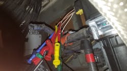
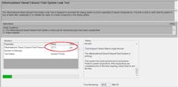
If you use bi-directional controls with the scanner, you can cycle the pump on and off to stress it. Doing it this way works better, so I hooked up my scope with a breakout lead I made to look at voltage, ground, pump current, command, and speed of the pump (Figure 3). I then initiated the dosing unit leak test with Cummins Insite, the factory diagnostic software. It took a few tries of cycling the pump, but I finally saw what I wanted to see.
The results
Below is how the scope is sampling from the vehicle:
- Green = on the feed wire
- Yellow = on the command wire
- Blue = pump Current
- Red = the speed signal
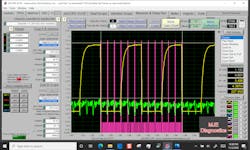
As could be seen on the capture, the voltage trace is dropping out, but since the yellow trace is covering it, you cannot see the entire voltage trace, so I omitted the capture. Since two of these signals are pulse-width modulated (PWM) I use the PWM-function of the eScope (by Automotive Test Solutions) to see the duty-cycle percentage of the command signal. This provides me two important pieces of information, regarding the command signal to the pump:
- Monitoring for signal-dropouts
- To know if the computer is maxing-out the pressure command

On this system, the computer commands a 90 percent duty-cycle during a DEF system leak-test. As you can see, the computer is commanding 90 percent, so we know that the computer has good control (Figure 4). The computer is in good control because I have scoped known-good vehicles and know that the computer is supposed to give 90 percent duty cycle during this bidirectional test when it first starts to build pressure in the system. After the computer sees that the pressure has built up to roughly 127 to 130 psi, it then decreases the command signal to a 10 percent duty cycle, which will maintain the system pressure.
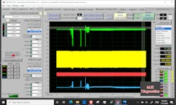
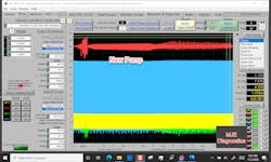
The benefit of the PWM function can also be seen in Figure 5. Notice how the capture is all blocky and meshed together? This is because I had a very large amount of time on the screen of the scope. That is why the capture looks like a big block graph.
Well, with the PWM function, it graphs the entire capture, so if you have a glitch in a signal, it will show up on the screen because the duty cycle graph will not be appear stable. A duty-cycle controlled signal should appear linear. If it does not, you will see sudden changes in the signal (going downward or upward).
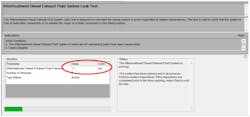
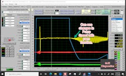
We also see that it has a good speed signal as well. For the ground, I am hooked up to the ground with my scope, so I have an extra channel. That way I can see the current of the pump as well. Also, the Insite software is showing the pump is creating pressure and primed, but the pressure on the scan tool screen is at 1.1 psi.
If the system is at pressure, which should be 127-130 psi, then it should not show 1.1 psi. The text in the status box is contradicting if the system is primed or not. This test has a glitch (Figure 6). The pump was building pressure, but the software put out false data. Glad I have a scope to verify the actual problem.
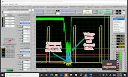
Clearly, we can see the drop in voltage, so now the question I bet everyone will ask is what about the rest of the capture? As I zoomed in on the capture in Figure 7, I noticed that as the voltage dropped, the current increased to 12.5A (which is way too much for this pump), and at the same time, it kept the command signal low. By this, I mean that when the current went high to 12.5A, it brought the command signal voltage down, which caused the computer to see a low voltage when there should not be a low voltage.
Instead, it should show a 20V square wave command signal. The excess current of 12.5A from the pump did this to the command signal. On initial prime of this 24V pump, it should not go over 4.5A. As it steadies out, after it reaches prime, it should be no more than 800mA to 900mA.
By these readings, it is indicating to me that the pump is internally shorting to ground, causing this problem. Also, it makes sense with the DTCs because the voltage feed goes to the pump, as well as the feedback signal. The pump is the common point that is bringing all these circuits down.
New pump
I installed a new pump, and the voltage did not go below 21V on the initial turn on, and there are no more DTCs stored for the relay feedback circuit or command circuit (Figure 8). I have also marked rulers on the current waveform to get the RPM of the pump (Figure 9). This pump has 12 field coils on it, so, I counted out 12 coil current humps and then multiplied frequency by 60 (because there are 60 seconds in a minute), which equates to 13,677 RPM for this pump.

I know this unit has 12 coils because I took the pump apart and visually inspected it. You can also see that the degree rulers line up with each negative transition of current that the pump produced. You can also see that the current waveform transitions have three coil current peaks in each hall effect window of the speed sensor.
To get a full revolution of this pump, it has to go through two transitions on the hall effect speed sensor (because those two transitions line up exactly with 12 current humps from the brushless pump). As I have stated before about the new PWM function of eScope, you can graph it now to see changes in PWM signal. This can be used to see if what the computer is commanding is actually true or not.
By knowing the speed of the pump, we can look at the command signal and see if it corresponds or not with the speed. If you think you have a pump that is turning too fast, you can match it to your known good with the PWM function to verify if the pump has proper command and speed.
I used it on the speed sensor to help me see changes in pump speed (Figure 10). This technique also gives you a better shot at finding a fault because you have more time on the screen, and with the eScope circular buffer, you don’t have to worry about missing data, so take advantage of this function. I use it quite often, and it gives me a better chance of finding intermittent faults.
These techniques can be used on any type of DEF pump, and they will help you save time and diagnose correctly. After the new pump was installed, we finally got a good pressure reading while doing the DEF system leak test (Figure 11). We also had to put another new pump on because the first replacement pump received initially was bad out of the box.
Experience is one of the best teachers in life, and hopefully my experiences will make yours less painful in your bay.
About the Author

Michael Eilbracht
Michael Eilbracht is a transit bus technician for the Champaign and Urbana Mass Transit District in Urbana, Ill., and is the owner of MJE Diagnostics, a heavy-duty mobile diagnostic and training business. He is also an ASE Certified Master Transit Bus Technician and also holds an Advanced L2 Certification.