Understanding diesel after-treatment systems and how to repair them
Once working in the automotive industry as a technician I'm sure many of you have had the opportunity of working on a diesel-powered vehicle. Many technicians can be intimidated by these vehicles (just like an EV, CNG or a hybrid vehicle). The only difference with these types of vehicles is that they are, well, “different.” You have been trained to work on gasoline-powered vehicles so that makes you more familiar with them. A diesel-powered vehicle can become second nature to you as well, providing you have adequate training. Let's face it, with today's ever-increasing technology in our industry, training is the most important tool we can obtain.
What gave us our greatest challenges on gasoline vehicles was the addition of emissions control devices that accompanied the basic gasoline engine. After the emission protocols that were introduced for the sake of keeping a clean environment, they also added computer-controlled emission components. Well, I'm happy to inform you that they have done the same with the diesel engine. The biggest thorn in the side of a diesel vehicle owner is the added emission control system, known as the after-treatment system. Service technicians have experienced the challenge of servicing a diesel vehicle's after-treatment system. The biggest challenge for a technician working on these types of systems is the lack in understanding of how these systems work, what components are in these systems and where to start their diagnostic process. Below is a vehicle that I worked on that had a problem with a certain component in the after-treatment system.
Today’s challenger
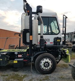
A 2020 Tico Pro Spotter truck with a 6.7L Cummins QSB engine (Figure 1), which is used to shuttle containers to and from a cargo ship, came into the shop. Even though this vehicle is not driven on our highways, by law it has to run clean emissions. This vehicle has an after-treatment system installed by the manufacturer (Tico) and has been coupled to the Cummins engine. For the most part, the components that comprise the system are made by Cummins. The after-treatment system is monitored by the ECM, but is interfaced with both the Cummins and Tico wiring harness. This is a common trait in the heavy-duty truck industry.
Many vehicles are assembled with multiple components used by different manufacturers and they have to tie-in their wiring harnesses together. Sometimes when you pull up a wiring diagram you might have to use several different ones to get all of the information you need. That can be challenging at times. On this particular vehicle, several components come into play in these types of systems. As I stated before, the after-treatment system is controlled by the engine computer. But what is an after-treatment system? An after-treatment system is a method or device for reducing harmful exhaust emissions from internal-combustion engines. In other words, it is a device that cleans exhaust gases to ensure the engines meet emission regulations.
So, this is how it works
The harmful emission gases in the exhaust stream move from the exhaust side of the turbo to the after-treatment system. On the Cummins system, the Diesel Particulate Filter (DPF) collects and oxidizes carbon to remove particulate matter (PM) by more than 90 percent; The Diesel Oxidation Catalyst (DOC) aids in this process and is also contained within the DPF. The exhaust passes from the turbo through the DOC and enters the DPF. After collecting the particles from the gases in the DOC and DPF, there is still nitric oxide (NO) and nitrogen dioxide (NO2) left in the exhaust. To reduce the NOx levels, a light mist of urea or Diesel Exhaust Fluid (DEF) is injected into the hot exhaust stream in the Decomposition Reactor. The exhaust progresses from the Decomposition Reactor into the Selective Catalyst Reduction (SCR) system. This converts the toxic NOx and urea mixture into harmless nitrogen gas (N2) and water vapor (H2O). This effectively eliminates harmful emissions, resulting in near-zero emissions from the exhaust.
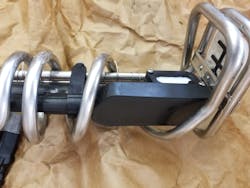
On this truck, there is a catalyst, diesel particulates filter, inlet and outlet NOx sensors (Figure 2), a couple of temperature sensors, a dosing module (Figure 3) and injector, a DEF tank module and a DEF storage tank. To make it easier I look at it in three sections:
· The catalyst section
· The particulates filter section
· The diesel exhaust fluid section
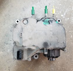
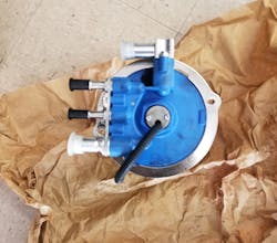
When a DTC is set, that code description will tell you what part of the after-treatment system is at fault. On this truck, there was a code 3866 “The after-treatment 1 diesel exhaust fluid quality,” stored as an active code in the ECM. An active code merely means that the fault is happening “now.” What this means is the after-treatment diesel exhaust fluid quality sensor (located in the DEF tank module (Figure 4) is a smart-device that communicates to the ECM via the J1939 data link. The after-treatment diesel exhaust fluid quality sensor performs its internal diagnostic checks and reports malfunctions back to the primary engine control module via the J1939 data link.
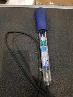
The after-treatment diesel exhaust fluid quality sensor is used to measure the concentration of the after-treatment diesel exhaust fluid in the tank. This sensor essentially measures the quality of the DEF fluid to see if the fluid is not contaminated. This sensor is not serviced separately from the DEF control module or tank sender unit. Fresh, 100 percent DEF fluid will measure at 32.5 percent. The DEF fluid can be tested using a refractometer or a suction tube type tool, similar to the tool that is used to check antifreeze strength (Figure 5). DEF fluid has a shelf life and can go bad if not used promptly or stored properly. When the DEF quality percent drops below a certain threshold, the MIL will be illuminated to alert the driver. If the vehicle is continuously driven with the engine light illuminated the vehicle will go into a derate condition where the driver will lose the accelerator function.
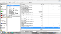
Now, remember this vehicle is a model-year 2020. So, if the DEF quality dropped below the correct value you would assume that the fluid is contaminated or compromised. Looking at our scan tool, you can see that the value is below 32.5 percent (Figure 6). I checked the DEF quality with the tester and was within spec. I inspected the inside of the tank for contaminants which the fluid sock would have picked up but there wasn’t any. So, knowing that, I felt it was time to check the DEF quality sensor for proper operation.
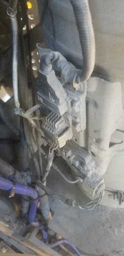
You can see the black box on the bottom of the sender is the module that houses the quality sensor, level sensor and the tank/fluid temperature sensor (Figure 7). On the bottom of that is the fuel sock filter. Hopefully, that will stop any contaminants before they hit the sensor module. Before I condemn a part and especially if it’s expensive, I like to make sure that the part is bad.
Proof is in the pudding
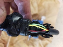
After reviewing the service information, it appears the tank level sender module is a simple setup. There isn't any adjustment whatsoever to be performed. This component has four wires going into it (Figure 8). The red wire is a 12-volt power feed and the Black wire is the ground. The other two wires are green and yellow. This is a twisted pair and they represent the J1939 communication network (the communication protocol found on most heavy-duty vehicles). The best way to test this component is with the unit still hooked up to the vehicle. I proceeded to use a lab scope for this test.
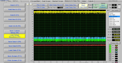
As you can see on the scope setup below:
· YELLOW= Channel , 12-volt power feed
· RED= Channel 2, circuit ground.
· GREEN= Channel 3, J1939 low circuit
· BLUE= Channel 4, J1939 high circuit
The 12-volt power feed and the ground circuits both appear to be good (Figure 9). The J1939 communication circuits are both good, as well. As you can see the data traces are clean, even and both about 2.5 volts (proper communication signal for this vehicle). So in reality, the quality sensor communicates over the J1939 network to the ECM. If the quality sensor is communicating properly and we are talking to it with our scan tool then the quality sensor is functioning. But in reality, the quality sensor is not transmitting accurate data to the ECM. Something internal to the quality sensor has failed as it isn’t reading the correct DEF concentration. This truck is a new model and the sensor should not have failed so prematurely. By testing every circuit going to the DEF level sender module, I knew with confidence that the shop needs to replace this component. This part is still under warranty. The shop replaced the part and informed me that the proper DEF quality has returned and the engine light was extinguished.
Proper testing of a system and its components are critical in today’s vehicle diagnostics. It doesn't matter if it's a light-duty or heavy-duty vehicle. Understanding how a system operates is key to a successful repair. That’s why I can’t stress this enough. Every technician who works in the automotive industry regardless of experience has to continue their education. Training will stop when technology stops. We all know that’s never going to happen. With the proper training and using tools that are up to today’s standards, you too will be successful when that job arrives in your service bay.
About the Author

Edwin Hazzard
Contributor
Edwin Hazzard owns South East Mobile Tech in Charleston, S.C., a mobile diagnostic and programming service providing technical service to many automotive and body repair shops. He has 35 years’ experience in the automotive industry. He currently is an automotive trainer, board member of TST and many other automotive affiliations.