Dealing with “no communications” codes can be a challenge, especially today when a single network can be host to numerous computers. Often, these issues can be traced to a failed module or hard fault in the bus wiring. But once in a while, the fault is intermittent - occurring with no cause readily apparent. How do you tackle either? With a little research, a wiring diagram or two, and a diagnostic plan!
Controller Area Network bus review
Typically, the CAN network uses a pair of twisted wires to connect various modules together so that they can share information and instructions. One wire is referred to as CAN High while the other is CAN Low. Both wires have a 2.5V bias when no communications are taking place. The difference between the two is what happens when a module starts talking.
The voltage on CAN High is brought up approximately 1V (to 3.5V) while CAN Low is brought down 1V (to approx. 1.5V). To establish the bias, two 120-ohm resistors are used and wired in parallel to the bus. These are the termination resistors and one of the first tests you were likely taught was to measure the resistance of the bus using your ohmmeter. But making that your first stop is not necessarily a good idea, and for two good reasons.
First, you must disconnect the battery and doing so could require you to perform relearns or reinitializations on a variety of systems. If you don’t know that going in, or you aren’t prepared to perform them, that simple mistake could end up costing you time and money. Second, on some models, you can’t access the bus through the DLC - it’s protected by a secured gateway module. Testing at the DLC without first consulting your service information could provide you with inaccurate test results that will lead you away from the cause instead of toward it.
Instead, start your diagnosis by performing a full system scan. Note what modules are reporting a no communications issue.
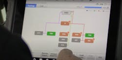
Many newer scan tools support some really handy functionality. In this case, not only can I perform the scan, but I can also see what modules are on each network. Odds are pretty good that the module causing the problem is the one on the network that doesn’t have a code set or shows a message of “no response”. Next, clear the codes and cycle the key off, followed by starting the engine. Perform another full scan to see if the codes return. If they do, it’s likely a hard failure and should be relatively easy to isolate. If not, then you may be dealing with an intermittent - and that’s going to take a bit more effort.
First, let’s define intermittent. Techs often call a problem they can’t easily reproduce in the bay an intermittent fault. But there really is no such thing. An intermittent fault is a fault that occurs under certain conditions (that you just haven’t learned yet). Identify the trigger for the fault and you’ll identify the cause.
Whatever form the no communications codes take, the first thing I like to do is peek at the CAN signal to see if it looks normal. A lab scope (or DSO= "Digital Storage Oscilloscope") makes this easy to do. Like the scan tools of today, some scopes have added functionality. The scope I'm using has a CAN bus inspection tool built in. This allows me to view either CAN High or CAN Low to see if any obvious issues are apparent. If I see something I don’t like, I can switch over to the scope module and connect to the network for a closer look.
What can the scope show us?
Start by connecting to the network. First, check your service information system and look at the bus diagram. Determine where the DLC is located on the diagram and identify the CAN High and CAN Low pinouts (pins 6 and 14 of the DLC) and follow them out to see what module or modules they connect to. If there appears to be a direct connection to the ECM and other modules on the network, you should be OK testing at the DLC. If it goes to a module that also has other networks connected to it, that is likely a gateway module and you may or may not be able to access the actual CAN network at the DLC. If that’s the case, you’ll need to identify a module you can easily access on the network and tap into the bus there.
For simplification, I’m using a 2005 Ford F350 as a guinea pig. Access to the CAN network is easily made at the DLC. And there are two ways you can connect here. The best way to connect is using a breakout box designed for the Diagnostic Link Connector. This prevents us from doing any damage to the DLC connector. I'll connect both grounds to Pin 5, and then I’ll connect one channel to Pin 6 for CAN High and Pin 14 for CAN Low. They are directly opposite of each other on the DLC. If you don’t have a breakout box, be sure to use a breakout lead or make two using the correct pin for the connector. Too large will damage the connector fit and too small may cause an intermittent contact that will affect your test results.
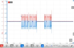
After connecting to the DLC, it’s time to set up the scope. I want a 20V range on the vertical voltage scale; 20 milliseconds per division (or a total of 200 milliseconds) across the horizontal time scale. Then, turn the key “on” and see what you’ve got. Use the time and voltage scales to adjust the pattern for easier viewing. This is what a normal pattern should look like (both starting at 2.5V, with CAN H being pulled up to 3.5V, and CAN L being pulled down to 1.5V, when communications are occurring) (Figure 1).
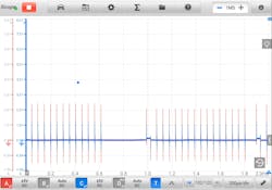
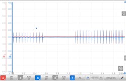
Notice the slightly higher spike near the end of the individual messages. This is normal and not of concern. What is of concern is when you see a pattern like this one (Figure 2). If both lines are reading 0V, it is an indication that the bus is shorted to ground. A pattern like this one, with both reading 2.5V, is caused when the bus has shorted to itself (Figure 3).
A loss of a termination resistor will still allow messages to be sent but individual message packets may be missed, at random. The baseline may also have a wavy appearance instead of a straight, clean line. A common issue is caused by corrosion in the module connectors, causing higher resistance in the bus. In that case, look for a pattern that looks dirty (that is, the transitions are not clean and sharp but more rounded).
Here’s a tip
To more easily identify if a problem exists (and something you can use to find those pesky intermittents), many newer scopes offer an ability to plot math channels. it allows you to manipulate the data the scope is reading. In this case, I’m going to configure a math channel to add the two CAN bus signal channels together; and when I make the selection, you can see a third pattern appear on the screen. This third channel is the result of the math channel.
This is not a new channel but the visual display of the two together. Normally, the CAN network has a bias of 2.5V, and the two (High and Low) are reflections of each other. Whether the bus is quiet, or the modules are chattering back and forth, adding the two should always remain at approximately 5V.
Next, start operating systems, opening doors, moving the steering wheel, even test drive the car, and monitor that pattern. If you see anything other than a relatively clean, flat line at 5V, a problem in the bus is likely. Use the record function of the scope to catch the intermittent in the act and to more closely inspect the CAN H and L patterns for further diagnostic direction.
Diagnosing no communications faults can be a challenge but armed with information and the right tools, finding the cause and making the correction will be a lot easier.
About the Author
Pete Meier
Former Creative Director, Technical | Vehicle Repair Group
Pete Meier is the former creative director, technical, for the Vehicle Repair Group with Endeavor Business Media. He is an ASE certified Master Technician with over 35 years of practical experience as a technician and educator, covering a wide variety of makes and models. He began writing for Motor Age as a contributor in 2006 and joined the magazine full-time as technical editor in 2010. Pete grew the Motor Age YouTube channel to more than 100,000 subscribers by delivering essential training videos for technicians at all levels.
Connect with Pete on LinkedIn.


