Computerized fuel injection, intelligent carburetion
Content brought to you by Motor Age. To subscribe, click here.
What you will learn:
• The carburetor had to fuel the engine properly under all operating conditions
• The computerized fuel injection system replaced the carburetor because it offered much better fuel control
• All the sensor inputs are processed by the ECU to create a proper output; "fuel injector pulse width"
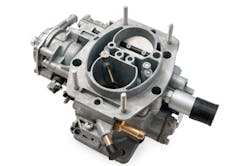
The carburetors of years past did a tremendous job of propelling down the road the heavy steel beasts that we used to call automobiles (Figure 1). For decades, it was the fuel delivery method used for gasoline-powered engines by most automobiles, recreational vehicles, and power equipment. The carburetor still does a fantastic job of accomplishing that goal. Proof of that is its wide use in racing circuits around the world even today. However, if power output were the only goal, we likely would not have realized the birth of the computerized fuel injection systems we’ve come to know over the past four decades or so.
The history of fuel delivery
A properly tuned carburetor did a fantastic job of keeping our gasoline internal combustion engines running strong and fuel-efficient. To accomplish this task, these purely mechanical devices relied on pressure differential as the incoming air from the atmosphere passed the carburetor’s jets. Designed as venturis, these jets would spill liquid fuel into the passing airstream, which would help to atomize the liquid fuel. As the air/fuel charge made its way through the intake runners of the manifold and into the intake valve ports, the now homogenized mixture would enter the combustion chambers and lie in wait for the ignition event to initiate the combustion process.
For the carburetor to accomplish the tremendous task of satisfying the engine’s demands under all operating conditions, different fuel supply circuits were in place within the carburetor assembly. What follows describes a smaller motorcycle carburetor’s construction, but the idea is the same, to maintain the appropriate air/fuel ratio under all operating conditions.
The float circuit was there to accomplish two goals. First, when float height was adjusted properly, to ensure there was always some reserve fuel within the carburetor (for a high-demand acceleration or a sustained high-load pull, perhaps up a hill). The second goal was to prevent the carburetor from overfilling and either slugging the engine with non-compressible liquid fuel or spilling excessive fuel down the outside of the carburetor (again, a motorcycle carburetor). So, it always maintains a full (but not overfull) carburetor bowl.
The idle circuit or pilot circuit existed to supply adequate air/fuel ratio at periods of closed throttle (idle) and very low throttle angles (maybe about 15 percent throttle). The circuit was metered by a jet. The larger the jet diameter, the more fuel this jet would provide, per given incoming air volume. This allowed the engine to be stable at low engine speeds.
The midrange circuit provides fuel during increases in throttle demand (greater than that 15-20 percent angle). As the throttle plate opens, more air enters the carburetor. Simultaneously, a tapered needle (which fits inside another fuel jet) is shuttled and more of the fuel stream is exposed to the venturi. This allowed for more fuel to more closely match the increase of incoming air.
The main metering circuit houses the main jet. This jet is very large in diameter, as the tapered needle I just spoke of fits inside it. Under wide throttle angles, the needle is drawn out of this jet and allows very little restriction to fuel flow into the carburetor’s throat. This, of course, provides the fuel needed under heavier loads.
The accelerator pump circuit does what it says. Since under transient throttle conditions the air entering the engine moves at a different rate than the fuel can be delivered, this pump squirts an added dose of fuel with the throttle blade’s movement. This circuit is particularly helpful under rapid increases in throttle angle and prevents what many of us have experienced when mowing our lawns. Take notice that if the throttle lever of a lawnmower is too swiftly shuttled, the idling engine will tend to stumble before it accelerates. This is due to a momentary lean condition, as these carburetors aren’t typically equipped with an accelerator pump.
The choke circuit exists to provide a richer fuel mixture during cold start-up. This could occur by adding additional fuel or limiting the amount of incoming air (either method will create a richer air/fuel ratio). A cold engine requires additional fuel because the chill tends to condense the fuel and not allow it to vaporize. Only fuel in a gaseous state will combust. The additional fuel of the choke circuit overcomes that issue. As the engine warms, the fuel will become more volatile and evaporate on its own. Therefore, the choke circuit will no longer be needed.
The evolution of fuel delivery
After decades, an air quality crisis arose from running vehicles and other sources of pollution. A substance known as photochemical smog was caused by pollutants reacting with sunlight. It created a haze over metropolitan areas like Los Angeles, which made it difficult to see but also very uncomfortable and dangerous to breathe, along with acid rain. (Figure 2).
The birth of the Clean Air Act was a result. This forced the hand of the manufacturers to produce cleaner-running vehicles. Mandates resulted in a reduction of tailpipe emissions and the addition of evaporative emissions and such pollution controls in automobiles. The computerized fuel injection system was another result. Computers are not smart. They simply process a lot of data very rapidly. That is exactly the job of the ECU (electronic control unit):
- To receive inputs from sensors, representing physical quantities (pressure, temp, angle, weight)
- Process the data (decide about how to deal with current engine operating conditions).
- Generate an output (create an injector pulse width [INJPW] to deliver the appropriate fuel).
So, this shouldn’t be rocket science. However, many technicians have been struggling to understand computerized fuel injection, and as a result, driveability issues tend to be the average shop's worst nightmare. These issues tend to eat up most of the workday (sometimes, the work week!), and the frustration that follows causes technicians to offer their “best guess.” And we know all too well how that story typically ends. So, why not take the time to back up and master the basics? Well, that’s just it; it takes time, but I will demonstrate. As mentioned above, fuel injector pulse width is the result of an equation (yes, math). And believe it or not, delivering the fuel to the cylinder is quite the easy part. Think about it like this:
- The engineers that designed the fueling system, thorough testing, realize the flow rate of the fuel injectors, themselves.
- They know what the fuel pump is capable of discharging (at a known wattage).
- They know how much latency exists between actual injector turn-on and when the injector physically shuttles.
Where does the real challenge lie? Accurately determining how much air entered the cylinder. It’s the job of the ECU to maintain an adequate air-fuel ratio under all rpm and engine load ranges (sound familiar?). This is where the math comes into play. The inputs exist to provide data to the ECU about the instantaneous operating conditions.
‘Inputs’ equal ‘current operating conditions’
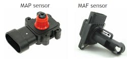
Mass Air Flow (MAF) or Manifold Absolute Pressure (MAP) sensors: These devices serve two very different strategies to determine the gram weight of the incoming air (Figure 3). One takeaway is that MAF is a direct airflow measurement and MAP is an inferred value. The difference in pressure between that inside the intake manifold, and the atmosphere, determines how hard the atmosphere is pushing on the throttle plate. “Vacuum” is caused by the pistons displacing more air than the throttle plate (restriction) is willing to allow. That is what the MAP is reporting, the differential between the manifold and the barometric pressure.
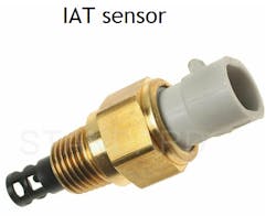
Intake Air Temperature Sensor (IAT): This device is a negative temperature coefficient thermistor, and its input represents the temperature of the incoming air (Figure 4). The significance is that air is denser when it is cold. This means more, cold air can fit in a given space than can warmer air. The equation to determine air mass is to multiply the density of the incoming air, by the volume, as measured by the MAF (Mass=Density x Volume).
Coolant Temperature Sensor (ECT): Like the IAT, the ECT is a thermistor. However, this one references the temperature of the engine (via the coolant). The significance is that a cold engine surface limits gasoline’s volatility (its ability to evaporate). When an engine’s cold, additional fuel must be delivered to compensate for this lack of volatility. As the engine warms, this negative characteristic is less of an issue so the additive fuel factor for a cold engine will taper off as well. At approximately 170 degrees F, there is no need to add any additional fuel to compensate for temperature.
Throttle Position Sensor (TPS) and Accelerator Pedal Position Sensor (APP): These are there to represent the driver’s intent. In years past, a step on the gas pedal tugged a throttle cable (that is a “command” to the throttle plate) however, we now “request” the throttle to open, with input to the ECU, from the APP (Figure 5). The significance is transient conditions are difficult to fuel properly for. As a result, tailpipe emissions suffer the most during these changes in throttle position. With the input now being a request, the ECU can anticipate the proper fuel enrichment for the requested input, before the throttle is moved, and maintain better control of the tailpipe emissions.
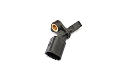
Crankshaft/Camshaft Position sensors (CKP/CMP): Both these inputs report the angle space of their respective shafts (Figure 6). This provides input about the cylinder position, speed of rotation, lack of cylinder contribution (misfire), and the phase of the camshaft (TDC of the compression stroke vs. TDC of the exhaust stroke), simply because there are two crankshaft rotations in every cycle of a four-stroke engine. These determine the timing of the injectors and how frequently to fire them.
All the above inputs are chewed up and spit out by the ECU (processed, to determine operating conditions/create an INJPW output). To hammer home the point, it really is a simple process. It just takes stepping back and understanding (as we have done) to become efficient at evaluating this data.
Parameters for proper enrichment
As is almost always the case, the noose of emissions standards is tightening, and it's why computerized fuel injection systems have come to be. So, to replace the carburetor with a system of stricter fuel control (in all load/rpm ranges), the computerized fuel injection system operates on six basic fueling strategies.
•Start-up enrichment: This mode responds to input for starter operation only. The INJPW is modified to accommodate the cranking engine and provides extra fuel. This is accomplished by either increasing INJPW duration and/or adding additional pulses, per cylinder, each engine cycle.
•Warm-up enrichment: This mode responds to input from the ECT, as discussed earlier. It accommodates a cold engine and its effect on a fuel’s volatility (ability to evaporate). Enrichment is heavier with cold temperatures and tapers-off as the engine warms, up to approximately 170 degrees F, when additional enrichment is no longer necessary.
•Density enrichment: This mode responds to input from the IAT, as discussed earlier. Colder air is denser therefore, more of it can fit into a given space when compared to warmer air. It is a critical factor in determining the gram-weight of the incoming air. Combining with input from the load sensor (MAP or MAF), this equation can be derived: Air mass = Density x Volume [Air mass = IAT input x MAF input or MAP input].
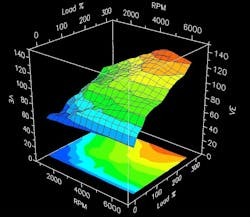
•Volumetric efficiency enrichment: The way an engine breathes is not linear, meaning throttle angle and rpm are not the only factors in “breathability.” Each engine design breathes differently, and contrary to popular belief, is actually more efficient below peak rpm. For that reason, engines are mapped out during engineering and initial testing to determine their rates of efficiency under all rpm/load operating ranges. This information is programmed into the ECU so it can adjust INJPW based solely on how efficient the engine breathes in each of those load/rpm operating cells (Figure 7).
•Acceleration enrichment: Transient conditions like changes in throttle angle are the running conditions most likely to cause excursions of the air/fuel ratio (loss in fuel control) that result in excessive tailpipe emissions. The TPS/APP provides input to changes in throttle angle and the rate of change. Because air moves at a different rate than that of fuel, the fuel INJPW changes with APP/TPS input. This prevents the loss of fuel control and replaces the accelerator pump circuit of the carburetor.
•Deceleration enleanment: During rapid closing of the throttle plate, fuel delivery would otherwise tend to be extremely rich, leading to excessive tailpipe emissions and exhaust backfiring. To prevent this from occurring, the ECU responds to this rapid change in APP by canceling all INJPWs. As a result, the engine begins to slow with no combustion taking place. This drastically impacts MPGs as well.
Together, with the feedback systems in place (Heated Exhaust Gas Oxygen Sensors/Short Term + Long Term Fuel Trim), the engine is more likely to be fueled correctly under all operating conditions. Even when the ability to fuel correctly fails, the corrective factor comes into play and compensates for any deficiencies.
Short-term fuel trim responds directly to the changes in the HO2Ss/AFRs. This is to compensate for any deficiencies detected in the exhaust stream. Over time, the deficiency is learned, and the long-term fuel trim will make that correction, sending the short-term fuel trim back toward “zero correction.” At, this point the deficiency is anticipated and compensated for before the combustion event occurs. This strategy prevents the deviation away from proper air/fuel ratio from occurring at all. And as a result, the tailpipe emissions remain at a minimum.
Catalyst operation
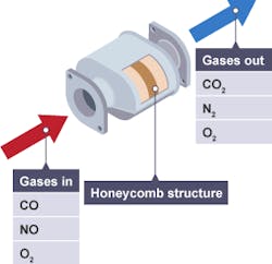
Within the exhaust stream lives the catalytic converter (Figure 8). This serves not as a “shop vac,” but more of a “dustpan” to further clean the engine’s emissions. This delicate device functions due to chemistry and heat, or what I like to describe as an “oven, in self-cleaning mode." It exists to manage three very harmful gases. These are oxides of nitrogen (NOx), hydrocarbons (HC), and carbon monoxide (CO). A combination of precious metals and the CO/HC from the engine allow the catalyst to chemically disassociate the NOx. It “splits” the nitrogen from the oxygen molecules. The nitrogen simply continues out through the tailpipe.
A different combination of precious metals and oxygen (leftover from the engine’s exhaust gasses/derived from the converted NOx) is used to oxidize (or chemically convert) the HC and the CO into less harmful gases (H20, carbon dioxide). The takeaway is that it takes proper fuel control to maintain the functionality of the catalyst.
As can be seen, it simply takes an understanding of whatever system you are faced with to analyze and diagnose a fault within that system accurately and efficiently. Computers are not smart; they simply do what they are programmed to do, and that is process inputs to create outputs. Your job is to pursue the root cause and correct the deficiency. Technology is going to continue to increase, and these systems are going to appear smarter as time goes on. The system described above is indeed about 40 years old. Whatever is to come, I can assure you, it will be here soon enough. Master the basics and grow that level of understanding. It will always serve you well.
About the Author
Brandon Steckler
Technical Editor | Motor Age
Brandon began his career in Northampton County Community College in Bethlehem, Pennsylvania, where he was a student of GM’s Automotive Service Educational program. In 2001, he graduated top of his class and earned the GM Leadership award for his efforts. He later began working as a technician at a Saturn dealership in Reading, Pennsylvania, where he quickly attained Master Technician status. He later transitioned to working with Hondas, where he aggressively worked to attain another Master Technician status.
Always having a passion for a full understanding of system/component functionality, he rapidly earned a reputation for deciphering strange failures at an efficient pace and became known as an information specialist among the staff and peers at the dealership. In search of new challenges, he transitioned away from the dealership and to the independent world, where he specialized in diagnostics and driveability.
Today, he is an instructor with both Carquest Technical Institute and Worldpac Training Institute. Along with beta testing for Automotive Test Solutions, he develops curriculum/submits case studies for educational purposes. Through Steckler Automotive Technical Services, LLC., Brandon also provides telephone and live technical support, as well as private training, for technicians all across the world.
Brandon holds ASE certifications A1-A9 as well as C1 (Service Consultant). He is certified as an Advanced Level Specialist in L1 (Advanced Engine Performance), L2 (Advanced Diesel Engine Performance), L3 (Hybrid/EV Specialist), L4 (ADAS) and xEV-Level 2 (Technician electrical safety).
He contributes weekly to Facebook automotive chat groups, has authored several books and classes, and truly enjoys traveling across the globe to help other technicians attain a level of understanding that will serve them well throughout their careers.
