Diagnosing Modern Cylinder Deactivation Systems
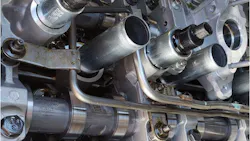
Variable displacement has evolved past a V8 switching between eight and four cylinders. Current systems may deactivate one cylinder, a fixed group, an entire bank, or almost any combination based on torque demand. The hardware also varies, with some engines using collapsible lifters, others switching rocker arms, and newer designs shifting camshaft lobe packs into a zero-lift position.
From the driver's seat, the goal is the same: reduce fuel consumption without sacrificing full-engine power. For the technician, however, each design requires a different approach. A GM AFM lifter fault is not diagnosed like an Audi sliding-cam problem, and a Honda VCM pressure-switch code does not automatically identify a failed switch. Cylinder deactivation is a series of separate events. The PCM issues the command, the electrical circuit operates the solenoid or actuator, and the valvetrain must complete the switch. Scan data may confirm the command while the hardware remains in the wrong position, and a normal current waveform does not prove that the hydraulic or mechanical action occurred.
Why Shutting Off Cylinders Saves Fuel
At light load, a gasoline engine doesn't need its full displacement. With the throttle partly closed, the pistons work against intake restriction, creating pumping loss. Deactivating selected cylinders allows the remaining cylinders to carry more load, so the throttle can open farther and reduce that loss.
Fuel is shut off to the deactivated cylinders, and both valves remain closed. The trapped charge then acts like an air spring as the piston moves. The challenge is making the transition smooth, which may require coordinated changes to fuel delivery, valve operation, throttle position, ignition timing, torque-converter strategy, and active engine mounts.
GM AFM, DFM, and the Systems in Between
GM Active Fuel Management is still the system most technicians associate with displacement on demand. On the traditional V8 application, cylinders 1, 4, 6, and 7 are deactivated, changing the engine from V8 to V4 operation. A Valve Lifter Oil Manifold assembly, or VLOM, contains four solenoids that direct pressurized oil through passages in the block to special intake and exhaust lifters. Locking pins normally couple the lifter's inner and outer bodies, so they move together. When the solenoid applies oil pressure, the pins release, and the cam follower portion can move without lifting the pushrod. The valve stays closed even though the roller part of the lifter continues to follow the camshaft. When the solenoid closes and the control oil is exhausted, spring pressure extends the pins, and normal lifter operation returns.
Timing is critical. The pins must move while the lifter is on the camshaft base circle. Low oil pressure, aerated oil, sludge, a leaking VLOM, worn lifter bores, or a sticking solenoid can delay the event. The pin then tries to move while the lifter is loaded by the cam lobe, which can damage the locking mechanism or leave the lifter partly collapsed. This is why replacing a failed lifter without checking oil pressure, the VLOM, oil passages, and lifter guides can result in another failure.
Dynamic Fuel Management on the L84 5.3L and L87 6.2L V8 is more involved. Instead of one manifold controlling a fixed set of cylinders, DFM uses an individual oil-control solenoid for each cylinder. The PCM can select fixed and rotating firing patterns and continually adjust the number of active cylinders according to torque demand. The engine is not simply changing between V8 and V4 modes.
The DFM solenoids are low-resistance units, approximately 0.7 to 0.9 ohm, driven with peak-and-hold current control. A scope pattern should show a rapid current rise, a peak period, a lower hold current, and a clean decay when the command ends. That proves the driver and winding operated, but not that oil flowed or the lifter released. A sticking spool valve, contamination, leakage, or mechanical damage can leave the cylinder in the wrong mode with a normal electrical pattern.
Vehicle identification matters. Some 2021 Silverado and Sierra trucks carry RPO YK9. These engines retain AFM- or DFM-related internal hardware, wiring, connectors, and fuses, but the PCM and software cannot activate cylinder deactivation. GM states that YK9 vehicles cannot be reprogrammed to turn the feature on. The hardware can still suffer a base-engine failure, but the absence of commanded deactivation is normal. GM also uses Switching Roller Finger Followers (SRFF) on the 3.6L High Feature V6 to deactivate cylinders 2 and 5. Oil pressure from the rocker-arm oil-control valves releases the locking mechanism, allowing the followers to create lost motion and keep the valves closed.
When a cylinder 2 or 5 misfire appears after an AFM event, moving the oil-control solenoids bank to bank can separate a solenoid fault from a mechanical valvetrain problem. If the fault moves with the solenoid, focus on the solenoid itself and the oil circuit it controls. If it remains on the same cylinder, verify valve lift and inspect the switching follower.
The 2.7L L3B four-cylinder uses a completely different design. Its Sliding Cam Valve Lift System provides high-lift, low-lift, and cylinder-deactivation profiles. Electromagnetic actuator pins engage grooves in the camshaft profile sleeves, and camshaft rotation moves the sleeves until the requested lobes are positioned over the followers. In the deactivation profile, cylinders 2 and 3 are shut down. Position sensors then confirm that each sleeve reached the commanded profile.
This system is not diagnosed like a DFM lifter problem. Scan data must be used to compare the requested profile, actuator-pin position, and profile-sleeve position. GM information released in 2025 addresses P30BF, P30C3, P30C7, and P30CB caused by possible sliding-lobe-pack binding. An actuator circuit can pass while the sleeve is mechanically stuck. During service, the actuator pins must be retracted before installation; the actuators should not be pried out or cleaned with solvent, and intake and exhaust units are not interchangeable.
Stellantis MDS
The Hemi MDS system is similar in principle to GM AFM. On 5.7L and some 6.4L engines, four oil-control solenoids deactivate cylinders 1, 4, 6, and 7 by directing oil pressure to the intake and exhaust MDS lifters. The pressure releases their locking pins, allowing the lifter bodies to telescope while the rollers continue following the camshaft, leaving both valves closed.
Shops continue to see camshaft and roller-lifter failures on both MDS and non-MDS cylinders. A Hemi misfire is therefore not automatically an MDS failure. Valve lift, pushrod movement, roller condition, and the camshaft lobe still must be verified. An MDS fault can appear normal during cranking because oil pressure may be too low to keep the lifters hydraulically collapsed, allowing normal valve movement and normal or relative-compression results. Once the engine starts and oil pressure increases, a leaking or stuck-open MDS solenoid can collapse the lifters and leave the cylinder deactivated even though the PCM didn't command it.
PCM software can also be part of an MDS repair. Stellantis has issued updates for certain Ram 5.7L eTorque trucks with MDS-cylinder misfires, deactivation DTCs, and rough running during warm-up, so programming software versions should be checked before the engine is opened.
Honda and Acura VCM
Honda and Acura refer to their cylinder-deactivation strategy as Variable Cylinder Management, or VCM. Earlier J-series V6 engines use oil-control solenoids and spool valves to route oil pressure through the rocker shafts to switching pistons. This releases selected rocker arms, so they create lost motion and keep the valves closed. VCM 2 could operate on six, four, or three cylinders, while later systems switch between six- and three-cylinder operation.
The design changed with newer DOHC engines. The 2023-up Pilot 3.5L and the Acura Type S 3.0L turbo both use VCM, but their valvetrain layouts and diagnostic procedures differ from the earlier SOHC J35. Identify the exact engine and follow the current service information before applying an older VCM test procedure.
On earlier hydraulic-rocker systems, the PCM monitors rocker-arm oil-pressure switches to confirm that the hydraulic circuit responded to the command. A P3400 or P3497 only shows that the VCM pressure feedback didn't match the command; it doesn't identify the pressure switch as the failed part. Low engine oil, incorrect viscosity, a restricted screen, debris in the spool valve, a sticking solenoid, excessive cold oil pressure, or an internal leak can prevent the expected state change. Graph the VCM command and pressure-switch PIDs together during the Valve Pause System test before replacing the switch. Honda has also documented cases where excessive cold oil pressure activated the spool valves even though VCM wasn't commanded.
Older VCM engines can develop oil consumption that fouls the spark plugs, causing misfires on the deactivated cylinders. The simple fix of new spark plugs usually fails, and the misfires return repeatedly and eventually damage the catalytic converters. On some earlier Odyssey and Pilot applications, Honda directs technicians to repair the engine (pistons and rings) rather than simply replace the plugs. Another common VCM fault is that the front VCM spool-valve assembly can also leak oil onto the alternator.
Honda uses Active Control Engine Mounts and Active Noise Cancellation to mask the vibration and firing-frequency noise created during reduced-cylinder operation. A failed active mount can make normal VCM engagement feel like a misfire or harsh transition. Excessive engine movement can also split the intake duct and create an intake air leak.
Ford Cylinder Deactivation
Ford introduced cylinder deactivation on the 2020 Escape 1.5L three-cylinder EcoBoost and added it to the Bronco Sport for 2021. The system was later phased out of the Escape but remained on the Bronco Sport through 2024. Ford also uses variable displacement on the 2021–2026 F-150 5.0L V8; Mustang 5.0L engines do not use this system.
The 1.5L deactivates cylinder 1, while the 5.0L controls cylinders 1, 4, 6, and 7. A solenoid directs oil pressure to a spring-loaded plunger in the rocker arm. When the solenoid is commanded on, oil pressure unlocks the rocker so camshaft motion is absorbed without opening the valve. Removing the command allows the rocker to lock, and normal valve operation to return.
Test the deactivation solenoids for supply voltage, PCM control, resistance, and current, then verify that the oil-pressure and rocker response match the command. Ford lists a resistance range of 5 to 14 ohms, depending on the application, and provides bidirectional controls. Ford Special Service Message (SSM) 50382 identifies the cylinder 1 deactivation solenoid as a cause of P3402 on some 1.5L engines. TSB 21-2158 addresses calibration-related rough running and deactivation DTCs on early-build 2021 F-150 5.0L engines, while SSM 51799 notes that some 1.5L models may produce a characteristic lugging vibration or boom during two-cylinder operation.
Mazda Cylinder Deactivation
Mazda introduced cylinder deactivation in North America for 2018 and used it on selected naturally aspirated 2.5L SKYACTIV-G applications, including the Mazda3, Mazda6, CX-5, CX-30, and CX-50. Availability varies by model year and trim. The system uses switchable hydraulic lash adjusters and rocker arms to stop valve operation under light load. Recall 3719F addressed an intake rocker arm that could move out of position during reactivation, causing a misfire, loss of power, stalling, or a no-start. Check recall and calibration status, then verify adjuster orientation and rocker position before condemning the camshaft or cylinder head.
Audi Cylinder on Demand and Other Limited-Volume Systems
Selected U.S.-market Audi models with the 4.0L TFSI V8 use Cylinder on Demand to deactivate cylinders 2, 3, 5 and 8 under light load. Rather than collapsing lifters, the Audi Valvelift System uses electromagnetic actuator pins to shift movable cam pieces on splined camshafts. This places a zero-lift profile over the followers, keeping both valves closed while fuel injection is disabled. A second actuator returns the cam piece to the normal profile.
Diagnosis therefore focuses on actuator operation, cam-piece movement, and position feedback. Aston Martin also uses cylinder deactivation on some U.S.-market 4.0L V8 models, though these remain uncommon in independent shops.
Putting the Diagnostic Pieces Together
Before testing, identify the system by RPO, build date, and service information. Displacement alone is not enough, especially on GM applications. Record all DTCs, freeze-frame data, and misfire history before clearing them, since they may show whether the fault occurred during deactivation, reactivation, or full-cylinder operation.
Most vehicles will arrive with a misfire, valvetrain noise, rough running, or a cylinder that remains deactivated—not simply a system that failed to engage. Start with the engine oil. Verify its level, condition, viscosity, and actual pressure at the specified temperature and RPM. Oil is the hydraulic working fluid for most designs, and low pressure, aeration, sludge, restricted passages, or incorrect oil can prevent the lifter, rocker, or actuator from switching.
The switching window is extremely short. At 2,000 RPM, each cylinder in a four-stroke V8 engine completes a cycle in 60 milliseconds. GM's DFM system can recalculate the cylinder deactivation pattern every 12.5 milliseconds, while Ford lists a 14-millisecond deactivation event. That leaves only a brief cam-base-circle window for the solenoid, oil pressure, and locking mechanism to respond.
After verifying oil pressure, compare the PCM command with the scan data. On hydraulic lifter or rocker systems, monitor the deactivation command and applicable oil-pressure switch. On sliding-cam systems, compare the requested profile with actual sleeve position. These PIDs confirm the command and response, but not that the lifter, rocker, or cam mechanism completed the switch.
Command the deactivation solenoid with the scan tool and check its current waveform while it's operating. Resistance testing can identify an open or shorted coil, while the current pattern confirms that the PCM driver and solenoid winding are working. It doesn't confirm that the internal spool valve moved, that pressurized oil reached the lifter or rocker, or the locking mechanism completed the switch. When the electrical test is normal, continue with oil pressure and mechanical testing rather than condemning the control module.
Relative compression is a useful diagnostic tool, but it may miss a fault that depends on running oil pressure. An MDS engine may show normal valve movement during cranking, then collapse a lifter or lifters after the engine starts and oil pressure rises. When cranking results don't match the running condition, use cranking vacuum, running compression, or an in-cylinder pressure waveform to confirm valve operation.
Mechanical inspection should follow the system design and test results. Check valve lift, pushrods, lifter rollers, guides, rocker locking mechanisms, cam lobes, and oil passages as applicable. On sliding-cam systems, verify that the sleeve reaches the commanded profile before condemning the actuator.
After major engine or valvetrain work, check the service information and complete every required relearn, setup, and calibration before confirming the repair. The procedures vary by engine, and missing one can set new DTCs or make a repaired cylinder-deactivation system appear to have another fault. Forgetting to perform the crankshaft-position variation relearn on a GM may set DTCs P3189 through P3190. Without the relearn, the cylinder named by the code may not be on the bank containing the actual valvetrain fault. Knowing pattern failures should guide the final inspection. On traditional GM AFM engines, a collapsed lifter or bent pushrod should not be treated as an isolated failure. Verify hot oil pressure, inspect the VLOM for internal leakage, replace its oil-filter screen, and clean the oil-feed passages. Inspect the camshaft, lifter guides, and oil pan for damage or debris that could cause a repeat failure. The VLOM filter applies only to AFM; DFM routes oil directly to the individual control solenoids.
On GM Gen 5 engines, verify that the correct oil filter is installed. The PF48E resembles the specified PF63, but its bypass valve opens at a lower pressure. Using the wrong filter can allow unfiltered oil and debris to circulate through the engine's tight-tolerance oil-control circuits. DFM doesn't use the traditional VLOM filter screen, making the correct main oil filter and a clean oil supply especially important.
Honda VCM faults often involve oil-pressure switches, restricted screens, sticking or contaminated spool valves, and rocker-control problems. VCM 2 engines are also known for camshaft wear, so replacing a pressure switch because it set a DTC may miss the actual failure (the base engine condition must be verified). Ford has had some issues with the cylinder one deactivation solenoid on the 1.5L EcoBoost, and some calibration-related complaints on the 5.0L F-150 applications.
The repair should not end when the failed part is found. The tech must decide why the lifter collapsed, the rocker failed to lock, or the cam profile didn't return to the position commanded. Verify the oil supply, inspect the known problem areas, check the PCM calibration, and confirm the repair under the conditions that caused the failure. The goal is not only to correct the immediate complaint, but to identify the cause and verify the repair so the vehicle doesn't return with the same failure.