What you will learn:
• Forward facing radar sensors are important to proper ADAS system functionality
• How a radar sensor works
• Why proper wheel alignment is so important
The forward-facing radar sensor is an integral part of the advanced driver assistance system (ADAS) on many vehicles. When calibrating the sensor, it is important to have some basic knowledge about how it works, system integration, and why it needs to have specific calibration routines performed.
In basic terms, a radar sensor works by bouncing radiation waves off objects within a space in front of the vehicle. This wave-like pattern operates in the “millimeter” spectrum and is considered to only operate via line of sight. Distances can be calculated by the time it takes the waves to travel to the object and back to the sensor, and location can be factored by the incident angles, a process known as triangulation. Finally, speed can be estimated using the Doppler effect – the change in frequency and wavelength of the waves in relation to the sensor's position.
Depending on the manufacturer, the radar sensor is typically part of a sensor suite used by the ADAS to “sense” the world around the vehicle and aid the driver by reducing certain driving tasks. Today, these systems are intended for assistance only, meaning the driver is ultimately responsible for the safe operation of the vehicle at all times.
A radar sensor is a delicate device operating in a harsh environment. Forward-facing radar is usually mounted at the front of the vehicle, which can lead to multiple challenges.
Calibration requirements for these sensors vary by manufacturer and may be updated over time. The component manufacturer relies on several calibrations for the sensor to function properly in all conditions. Some of these calibrations need to be re-established after certain services are performed on the vehicle.
Technicians have little to no control over some of these calibrations, however. For instance, some internal calibrations cover the sensitivity of the sensor in relation to temperature and typically don’t require any field calibration. However, it is possible that the manufacturer may discover issues with these calibrations that could potentially be resolved by updating the sensor’s firmware. It is important that the technician checks for applicable technical service bulletins and available software updates for these systems prior to performing field calibration.
When it comes to service, the technician will be responsible for performing certain calibrations as prescribed by the vehicle manufacturer. Field calibration typically relies on the technician establishing certain baseline values, so the sensor knows its position relative to 3D space (world coordinates) and the vehicle it is attached to.
Vehicles may require certain specifications prior to calibration, such as a minimal amount of fuel, tire size and pressure, and other factors that might affect the weight and balance of the vehicle. Consult the latest vehicle service information for requirements.
Case study
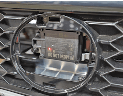
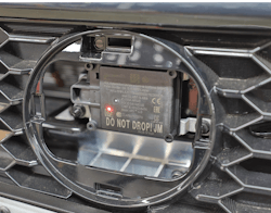
When working on a 2019 Nissan Altima, the service information states that the technician must always perform the radar alignment adjustment after removing and installing or replacing the distance sensor for intelligent cruise control (ICC). As mentioned earlier, these sensors are very sensitive and most include a large warning label stating not to drop the sensor (Figure 1).
Most component manufacturers state that if the unit is dropped, it should be scrapped and replaced. It is important to keep this in mind when performing such services. For instance, a technician may find themselves performing a radar calibration as a sublet for a body shop. They should be asking themselves, “Why am I calibrating this sensor?” If the reason for calibration was due to a collision, the technician may want to consider requesting a new sensor.
It is possible that a vehicle could have been involved in a collision without the sensor sustaining any visible damage. I have observed radar sensors that appeared normal but presented difficulties or were impossible to calibrate, ultimately requiring the sensor to be replaced. I’ve also seen sensors opened for inspection revealing internal damage.
Keep in mind that the service information may require that the vehicle undergo a proper wheel alignment with the thrust angle set to zero. When preparing for an alignment on a vehicle with ADAS, the technician needs to ensure that the vehicle is placed on a level surface and meets all other vehicle preconditioning states as outlined in the service information.
Here are a few tips that may be useful when tasked with ADAS calibration:
- Always perform a full vehicle scan for diagnostic trouble codes (DTCs) and make sure that all of the modules the vehicle is supposed to be equipped with are reporting. Some aftermarket scan tools may only show modules currently present on the bus system.
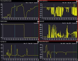
- Scan the system(s) and data parameters and record them. For forward-facing radar, pull up the distance and relative speed parameters and place them in graphing mode. Have an assistant ride along and observe the data while following other vehicles. If a very erratic signal is observed, this is indicative of a damaged sensor. Fig. 2 illustrates the performance of a damaged sensor. It is recommended that technicians scan several vehicles in order to gain knowledge and awareness of what’s normal and what’s not.
- When parking the vehicle in the bay, have the scan tool connected with the steering wheel angle data parameter displayed and set the steering wheel to achieve a 0° reading.
- A battery maintainer is strongly recommended to ensure the system voltage stays in a safe range.
The radar alignment process involves a reflector plate to be placed front, center, and square to the center line of the vehicle. Additional special tools are required in order to establish the center line of the vehicle relative to the rear wheels (thrust angle). You’ll find that the setup process is usually the biggest challenge. However, after performing several calibrations, technicians should find their efficiency improving greatly.
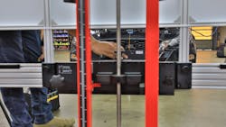
There are several aftermarket tools, such as the one shown in Fig. 3, which help streamline the process.
With the vehicle on a level surface and the alignment plate placed in its exact position, a scan tool will be used to request that the vehicle’s onboard systems execute an alignment calibration cycle. Once the request has been made, the system will establish its offsets based on the radar returns from the calibration plate. It is essential for technicians to take the time to set up the calibration tools properly. If everything is set up correctly and the onboard systems are in good health, the scan tool should report that the alignment is in progress followed by an indication that the alignment has been completed. Once complete, the technician should observe the following parameter identification data (PIDs) and check them against reference values:
- Vertical angle – radar angle
- Vertical angle – measurement result
- Horizontal angle – radar angle
- Horizontal angle – measurement result
- Alignment status
Please refer to the most up-to-date service information for the proper reference values.
If the alignment process is unsuccessful (and it will likely happen), the technician should double-check their setup. It is imperative that technicians take their time in setting up the vehicle and tooling properly in order to avoid these challenges. The manufacturer usually provides a troubleshooting guide as an aid, and technicians will likely develop their own over time. It might be worth studying these prior to attempting an alignment process.
If the calibration process has been completed successfully, the technician should look for the OEM action plan for verifying system operation. Nissan action plans are comprehensive and provide the technician with various tasks in order to test and validate system operation. As a best practice, an extended road test including a performance test of the system should be included as well. Follow this by performing a full system scan and generating a report for the shop’s records. A clean report with no issues should result in a properly repaired vehicle.
About the Author

Scott Brown
Founder - Diagnostic Network
Scott is an ASE Master Certified Automobile Technician with L1, L3, & L4 credentials and has over 39 years of professional service industry experience. As an independent shop owner in Southern California and with his engagement at various levels of within our industry, he continuously strives to move the industry forward through networking, education, communications, and training. Scott is a founder of the Diagnostic Network (https://diag.net/) which was born in 2018 after he retired after 22 years at iATN, where he served as company president.
Brown is also the host of Professional Tool and Equipment News (PTEN) and VehicleServicePros.com podcast, Torque Factor. The podcast addresses the latest automotive service technologies while focusing on expanding knowledge and awareness around tools, equipment, education, and industry trends.


