Some 2015 Ford F-Super Duty 450/550 trucks equipped with a 6.7L diesel engine, dual fuel tanks and built on or before May 5, 2014, may exhibit a discharged battery and a no crank/no start condition when the rear dual fuel tank selector switch is left in the on position. These conditions may be attributed to low impedance in the dual tank switch system.
- Disconnect the batteries (recharge as required)
- Remove the passenger right front cowl side trim panel.
- Remove G302 terminal screw and position aside. Disconnect connector C2280B from the body control module.
- Identify the gray/yellow wire from the relay kit. Strip 1.25-inch of insulation from the end of the wire.
- Connect the relay kit gray/yellow wire and pin terminal together. Use only the solder splicing method and protect the connections with heat shrink tubing. The heat shrink tubing supplied in the kit contains hot melt glue that creates a waterproof and airtight connection. In the relay circuits kit, the yellow/green and gray/blue wires are not used. Heat shrink the unused circuits supplied in the relay kit.
- Identify the yellow wire from the relay kit and strip 1.25-inch from the end of the wire.
- Identify the black ground eyelet pin terminal 10540. Strip 1.25-inch of insulation from the end of the wire. The black ground eyelet terminal can be located in the wiring harness terminal repair kit, box 4, drawer 14, terminal number 105460.
- Connect relay kit yellow wire and ground pin terminal 105460 together.
- On connector C2280B, slide the black connector cover back and insert the gray/yellow spliced pin terminal into empty cavity pin 5 of connector C2280B. Secure the pin in the connector and close the cover.
- Reconnect C2280B to the BCM (body control module).
- Reassemble G302 with relay kit ground eyelet and tighten the screw to 106 in-lb.
- Secure the relay kit in a vertical position to the existing radio antenna wiring harness tab.
- Reinstall the passenger side front cowl trim panel and reconnect the batteries.
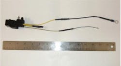
The relay kit is available as P/N AU5Z-14N089-FA. The wire terminal kit is P/N DU2Z-14474-AA.
About the Author
Information courtesy of Mitchell 1
Information for Technical Service Bulletins comes from ProDemand, Mitchell 1's auto repair information software for domestic and import vehicles. Headquartered in San Diego, Mitchell 1 has provided quality repair information solutions to the automotive industry since 1918.
