Component testing and cam and crank sensors
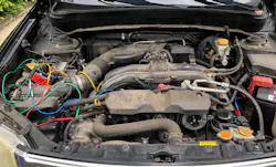
Modern engine management systems rely on precise sensor data to determine engine speed, position and timing. Two of the most critical inputs come from camshaft and crankshaft position sensors, which allow the control module to control ignition timing, fuel delivery and overall engine performance.
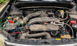
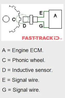
These sensors work in conjunction with a phonic (toothed) wheel, where each passing tooth generates a signal representing engine rotation. This allows the system to determine:
- Engine position within its cycle
- Cylinder identification
- Cam/crank synchronization
Accurate synchronization is essential for:
- Sequential fuel injection
- Ignition timing
- Emissions compliance
- Variable valve timing systems
Even small inconsistencies in these signals can disrupt performance, drivability and system operation.
Types of cam and crank sensors
Modern engine systems primarily rely on three key sensor types. Each produces a different signal, and understanding these differences is essential when interpreting system behavior.
Magnetic pulse generator
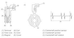
Magnetic pulse generators are a type of inductive (passive) sensor, meaning they generate their own voltage and do not require an external power supply.
They consist of:
- A permanent magnet
- A soft iron core
- A coil winding
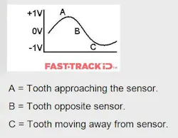
As the phonic wheel rotates, each tooth passes the sensor and alters the magnetic field. This change induces a voltage in the coil, creating an electrical signal.
Key characteristics:
- Produces an analog AC waveform (sinusoidal signal)
- Signal alternates above and below zero volts
- Voltage increases with engine speed (RPM)
- Typically, a 2 wire sensor
Because output is dependent on rotational speed, signal strength is lower at cranking speeds and increases as engine speed rises.
Half-effect switch
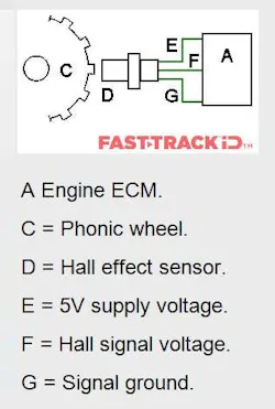
Hall-effect sensors are active sensors, requiring a power supply and ground to operate.
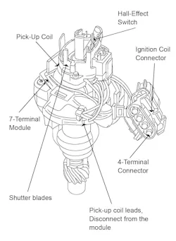
They use an integrated circuit to detect changes in magnetic flux caused by the rotating phonic wheel. As each tooth passes the sensor, the signal switches between high and low voltage states.
Key characteristics:
- Produces a digital square wave signal
- Voltage switches between fixed levels (e.g. 0V–5V)
- Signal amplitude remains constant regardless of engine speed
- Signal frequency increases with rotational speed
- Typically, a 3 wire sensor (power, ground, signal)
Because the signal remains stable even at very low speeds, Hall-effect sensors provide reliable and precise input for camshaft position and engine timing control.
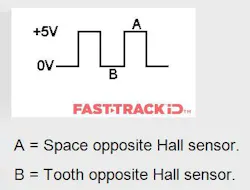
Hall-effect sensors produce a digital switching signal, toggling between high and low voltage states.
Unlike inductive sensors:
- Voltage amplitude remains constant
- Signal frequency changes with engine speed
Because the control module depends on clear switching thresholds, any issue that prevents the signal from fully transitioning, such as voltage drop, distortion or electrical noise, may result in the signal being interpreted as invalid.
This makes signal clarity critical, even when no obvious fault codes are present.
Magneto-resistive sensor
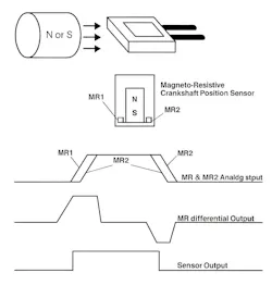
Magneto resistive sensors are a more advanced sensor type used in many modern systems.
They produce a digital output signal similar to Hall-effect sensors, but are more sensitive to small changes in magnetic fields.
Key characteristics:
- Digital square wave output
- Typically, a 3 wire configuration
- Highly sensitive to magnetic field changes
- Capable of detecting fine positional variations
Due to their sensitivity, these sensors can be affected by:
- Trigger wheel imperfections
- Mechanical wear
- Debris or contamination
Common issues: Real-world example: Chrysler 3.6L Pentastar
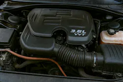
In some engine systems, such as the Chrysler 3.6L Pentastar engine, underlying mechanical wear can significantly impact sensor performance.
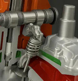
Components such as camshafts and rocker assemblies are subject to continuous contact. Over time, particularly where lubrication is compromised, this can result in the formation of fine metal particles due to steel-on-steel wear.
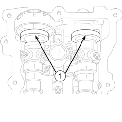
These particles circulate within the engine oil and can accumulate on magnetic components, particularly in systems using magneto resistive or Hall effect sensors. As contamination builds, it can interfere with the sensor’s ability to interpret the magnetic field accurately.

This can lead to:
- Irregular or unstable signals
- Diagnostic trouble codes
- Repeated fault conditions
In these scenarios, replacing the sensor alone may not resolve the issue, as the underlying cause remains within the system. This often results in the same fault condition returning after replacement.
Why signal accuracy is critical
The engine control module relies on accurate cam and crank signals to determine:
- Engine position
- Cylinder firing order
- Injection and ignition timing
If signal quality is affected through distortion, noise or incorrect voltage levels, the system may misinterpret the data, leading to:
- Diagnostic trouble codes
- Poor engine performance
- Starting issues
In many cases, the signal pattern itself is the most important diagnostic indicator, not just the presence of a fault code.
Scanner data vs. Actual signal behavior
Scan tools provide information that has already been processed by the control module. While useful, this represents the outcome of a condition, not necessarily the underlying cause.
Testing directly at the component level provides:
- Raw signal data
- Greater visibility of intermittent faults
- Insight into real-time system behavior
This is particularly important for cam and crank sensors where:
- The waveform is the diagnostic evidence
- Subtle signal issues may not be visible through scan data
Comparing live signals to known good patterns is key to understanding whether a component is operating correctly.
Why component testing is often overlooked
In many cases, component testing is delayed or skipped entirely.
Technicians may:
- Rely on fault codes alone
- Replace components based on assumption
- Delay signal validation until later in the process
This can result in:
- Misdiagnosis
- Unnecessary component replacement
- Increased repair time
- Vehicle comebacks
Component testing helps address this by encouraging earlier validation and more consistent diagnostic workflows.
This reinforces the importance of identifying the root cause of a signal issue, rather than focusing solely on component replacement.
Why use multiple scope channels?
When diagnosing cam and crank sensor signals, evaluating a single signal in isolation does not always provide the complete picture. Modern engine systems rely on the relationship between multiple signals, particularly camshaft and crankshaft position signals, to determine engine synchronization and timing accuracy. Viewing these signals together allows for a more complete understanding of how the system is operating.
Real-world example, 2011 Subaru Forester X
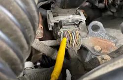
2. Subaru Forester Scope Crank Sensor
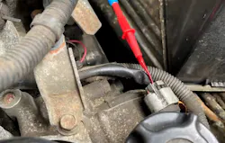
3. Subaru Forester Scope Cam Sensor Drivers Side
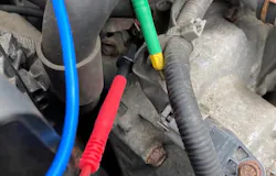
4. Subaru Forester Scope Cam Sensor Passenger Side
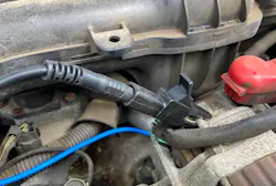
5. Subaru Forester Scope Setup Alternator Ground
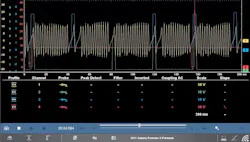
Using multiple channels enables the simultaneous observation of:
- Camshaft position signals
- Crankshaft position signals
- Related outputs such as ignition or fuel signals
This combined view provides valuable context, helping to identify how signals interact and whether they remain correctly aligned throughout engine operation.
For example, even if an individual signal appears normal on its own, comparing it alongside related signals may reveal:
- Timing inconsistencies
- Signal dropouts
- Loss of synchronization
- Correlation issues between cam and crank signals
This is especially important in systems where precise timing is critical for:
- Fuel injection events
- Ignition control
- Engine performance and emissions
By observing multiple signals together, technicians gain a clearer picture of system behavior, helping to distinguish between isolated component faults and broader system-level concerns.
Conclusion
Cam and crank sensors are fundamental to modern engine management, providing the data required for precise timing, synchronization, and overall system performance. Effective diagnosis requires more than identifying fault codes; it depends on understanding how these sensors operate and how their signals behave.
By focusing on signal patterns and system interaction rather than assumptions, technicians can more accurately identify root causes and avoid unnecessary component replacement. Guided Component Testing supports this approach by providing structured insight and reliable reference data, helping improve diagnostic consistency and confidence.