LIN Initialization: Data bus fundamentals and testing
Modern vehicles rely on interconnected networks to operate electronic systems efficiently. While high-speed Controller Area Network (CAN) handles critical engine, transmission, and drivetrain communications, low-speed networks such as Local Interconnect Network (LIN), J1850, and K-Line manage smaller body-related systems and diagnostic access. Understanding how these networks operate, their voltages, and signaling patterns is essential for accurate troubleshooting and repair.
Voltage differential
All networks operate on a voltage differential—the difference between a high and low voltage level—which represents data signals. For example, on a LIN bus, the module operates on the high side at 13.35 V and pulls down to 0.91 V on the low side. The differential of these values, around 12.44 V, forms the basis for reliable communication.
Data link connector
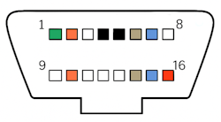
The vehicle’s diagnostic link connector (DLC) provides access to multiple networks:
- Pin 1: Low-speed CAN
- Pin 2: J1850 VPW / J1850 PWM +
- Pin 4: Scan tool power ground
- Pin 5: Common signal ground
- Pin 6: High-speed CAN +
- Pin 7: K-Line (Keyword)
- Pin 10: J1850 PWM
- Pin 14: High-speed CAN-
- Pin 15: K-Line L
- Pin 16: Scan tool battery +
Testing
Using a breakout box, technicians can quickly monitor all 16 DLC pins, check for shorts, reversed polarity, and live voltage readings. For example, CAN testing requires connecting to terminals 6 and 14. Tools such as the Blue-Point EECTBOB simplify access to all pins, eliminating guesswork and speeding up diagnostics.
Low speed networks: J1850
Before LIN, many manufacturers used J1850 as a low-speed communication network. Although largely replaced by CAN, J1850 is still found on older vehicles. It manages functions that do not require high throughput, such as central locking, lighting control, HVAC panels, instrument clusters, and alarm modules.
Two formats exist:
- J1850 VPW: single-wire, 10.417 Kbit/s, 7V differential
- J1850 PWM: dual-wire, 41.6 Kbit/s, 5V differential
Waveforms demonstrate that the two PWM lines mirror each other throughout each packet. For example, the high side of packet 1 reads 4.53 V while the low side drops to 0.55 V; packet 2 ranges from 5.04 V down to 0.22 V. This mirroring confirms the bus is switching correctly, showing the network is active and not shorted.
- Technicians will still encounter J1850 on pre-2008 OBD systems. Key points: slow communication speed makes scope captures easy, and intermittent faults often stem from poor grounds, shared grounds, or corrosion.
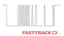
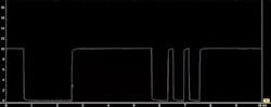
J1850 VPW bus
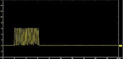
J1850 Variable pulse width waveform
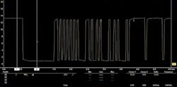
J1850 PWM bus
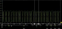
J1850 Pulse width modulation waveform
The two signal lines mirror one another throughout each data packet. In the first packet, the high side measures around 4.53V while the low side drops to roughly 0.55V, and in the second packet the values shift slightly, ranging from about 5.04V down to 0.22V. These variations are expected due to circuit tolerances, but the consistent opposite movement of the two lines confirms that the bus is switching correctly and that the network is not shorted, providing a reliable indication that the communication is active and functioning as intended.
Both formats use voltage transitions to represent logic states. As a low-speed network, timing was less critical than CAN, so modules could be produced at lower cost. However, as vehicles increased in complexity, J1850’s capacity became restrictive and eventually it was phased out in favor of CAN.
Applications today
Technicians will still encounter J1850 buses during diagnostic and electrical repairs on older vehicles. Useful points to remember:
- J1850 is always present on pre-2008 OBD systems as it formed part of the original OBD-II standard
- The diagnostic link connector (DLC) carries J1850 signals on Pin 2 and Pin 10 (for PWM) or Pin 2 only (for VPW)
- Slow communication speed means data traces are easy to capture on a scope.
- Intermittent faults are often caused by poor grounds, shared grounds, or corrosion at connectors
K-Line
K-Line, defined in ISO 9141 and ISO 14230, is a single-wire serial diagnostic link with a 10.65 Kbit/s rate and 10 V differential. Some manufacturers, such as Subaru, used K-Line into the 2010’s for module diagnostics. Its point-to-point design is slower than CAN, requiring precise wake-up procedures.
LIN bus: Local Interconnect Network
LIN was developed as a simple, low-cost alternative to CAN for localized body functions. It consists of a single master node (typically an ECM) and up to 15 slave nodes. LIN can communicate with CAN via the master, enabling integration across network types.
- Transmission rate: 20 Kbit/s
- Voltage differential: ~12V (high side 13.35V, low side 0.91V)
- Applications: body and comfort functions, including mirrors, seat motors, window regulators, steering wheel switches, and door locks.
Messages use dominant and recessive bits, similar to CAN. LIN’s low bandwidth is ideal for localized systems where real-time performance is not critical.
LIN is used wherever the bandwidth and versatility of CAN are not required. A LIN bus consists of a single wire with a transmission rate of 20 Kbit/s and uses a 12V differential. Timing is controlled by the master node, meaning slave nodes do not require quartz crystal oscillators, lowering manufacturing costs.
This is typically used for body communications such as ON/OFF communications.
- Steering wheel: cruise control, wiper, turn signals, climate control, radio
- Seat: seat position motors, occupant sensors, control panel
- Door: mirror, central ECU, mirror switch, window controls, seat control switch, door lock
Just as with CAN bus the messages are constructed using dominant and recessive bits. The bus recessive state is a logic 1 bit and represented by a bus voltage of 12V. The dominant state is a logic 0 and represented by a bus voltage of 0V.
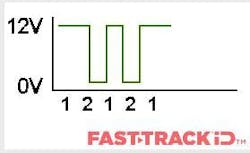
- Recessive state
- Dominant state
LIN signal has a high side of 13.35V and a low side of 0.91V
LIN ensures reliable control of these systems without high bandwidth or real-time processing, simplifying the vehicle’s electrical architecture. Its low-cost design allows manufacturers to use dedicated modules for localized tasks, such as all components in a driver’s door, without overcomplicating the network.
Practically, CAN offers several advantages in the workshop. It supports complex system interaction, enables fast diagnostic access, and reduces wiring demands by allowing modules to share data rather than running individual signal wires to each component. Fault-finding often focuses on voltage levels, termination points and checking for corrupted messages. When a CAN fault is present, multiple systems may report communication errors, making a methodical approach essential.
Controller Area Network (CAN)
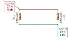
High-speed CAN uses two twisted wires with a 100–500 Kbit/s transmission rate and a 2–2.5V differential. It supports multi-master communication with message arbitration, ensuring critical signals are prioritized. Proper termination with 120 Ω resistors at each end of the bus stabilizes the network.
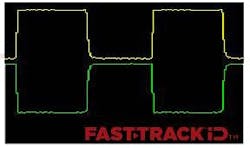
This is a typical known-good CAN signal. CAN low is a mirror image of CAN high. In all waveforms, CAN high is the yellow channel and CAN low is the green channel.
We want to see a flat horizontal line which is the idle voltage, and then packets of data, which are the square waves that represent a round trip for the data (transmit and receive). Each of the modules have quartz crystal clocks inside them and they can change the timings of the packets of data so they align.
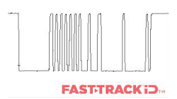
Here are examples of known-bad CAN waveforms:
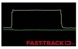
This waveform shows the CAN low signal wire in an open circuit state
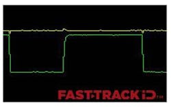
This waveform shows the CAN high signal wire in an open circuit state
Gateway module
Gateways route data between different CAN networks in the vehicle. When a pre-scan shows that major systems, such as the engine, transmission, body control module (BCM) and brake module—have lost communication while others, like the radio, SRS module and instrument cluster, remain responsive, the pattern suggests a problem with the gateway module. Loss of power, ground or internal failure at this point can prevent entire groups of modules from exchanging data, even though other parts of the network continue to function. Recognizing this behavior allows the diagnostic approach to focus on the network-management unit rather than testing each module individually.
Understanding LIN module initialization
LIN module initialization is critical whenever a component is replaced or serviced. It ensures the master ECU correctly recognizes and configures newly installed modules, similar to pairing a Bluetooth® device. Without initialization, modules may not function, and communication errors can arise.
Why initialization is necessary
Module initialization is a critical part of LIN communication, particularly when a new component is fitted during service or repair. The process allows the master ECU to identify the newly installed slave device, assign it a valid node address (NAD) and configure its communication parameters. Essentially, initialization acts as a discovery and pairing procedure, ensuring the new module integrates correctly with the vehicle’s control system.
What happens during initialization
Initialization is typically performed using a diagnostic scan tool, which sends LIN-specific commands and monitors the responses from the module to confirm proper integration. The procedure generally follows these steps:
- Wake-Up and synchronization: activate and align all LIN nodes.
- Discovery: query connected devices to determine their type, funciton, and capabilities
- Configuration: assign a new node address (NAD) and frame IDs.
- Verification: test communications to ensure successful pairing.
- Schedule update: update the internal message schedule to include any new frames.
Practice example: Ford Bronco LIN new module initialization
In the latest Snap-on diagnostic software release, LIN module initialization has been extended to 2021 and newer Ford Bronco models. This functionality enables:
- Automatic recognition of newly installed LIN components
- Correct assignment of node addresses and frame IDs
- Full verification and schedule updates without manual intervention
Technicians can now quickly complete LIN initialization on the Bronco, ensuring new mirrors, motors, or sensors communicate correctly with the master node, reducing diagnostic time and maintaining vehicle reliability.
Before performing this procedure:
- Park the vehicle on level ground
- Ensure the battery voltage is greater than 10V
Operational steps:
- From the vehicle systems menu, select body control module under body controls
- Select functional tests → special functions → LIN new module initialization
- This procedure will configure all BCM LIN nodes, including rear-view camera, intrusion sensor, rain sensor module and battery monitoring system
- Select Continue
- This procedure will configure all BCM LIN nodes such as rear-view camera, intrusion sensor, rain sensor module and battery monitoring system.
- Set the ignition switch to ON (position 1)
- The scan tool will run an approximately 15-second countdown to reinitialize the modules
- Procedure complete
Don't skip initialization
Technicians often access LIN networks via the DLC or a breakout box, monitoring voltages with a scope where necessary. A clear understanding of network topology, node roles and expected voltage differentials is essential for effective troubleshooting.
Key practical points:
- LIN operates as a single-wire bus with a differential voltage around 12V
- Switches, motors, and sensors rely on correct initialization to function
- Skipping initialization frequently leads to misdiagnosis; follow scan tool prompts and procedures precisely
Common pitfalls and issues if initialization is skipped:
Failing to perform LIN module initialization can prevent the master ECU from recognizing new or replaced slave modules, causing communication errors and improper system behavior. Typical issues include:
- Devices not responding, such as mirrors, window motors, seats, rear-view cameras, or climate controls
- Safety and comfort sensors (e.g., rain/light sesnors, seat occupancy sensors) not functioning
- Battery or energy management modules reporting faults
- Communication malfunction codes: Generic U-series codes indicating LIN bus issues, such as U1008, U1112, U150B, U150C, U1511, U1512, U1514, U1515. Specific examples include U0215 (P/W SW (DR) LIN timeout), U0231 (rain/light sensor LIN timeout), and U1109 (Column SW LIN timeout)
- “No Response” or “Lost Communication” Codes: Indicate that the master module did not receive expected data from an uninitialized slave node within the timeout period. Examples include B2786 (no response from steering lock ECU), B2789 (no response from ID BOX) and B278C (lost communication with power source control)
- Intermittent faults or unexpected behavior that appear unrelated to the replaced component
LIN module initialization restores proper communication between the master ECU and newly installed slaves, ensuring full system functionality and preventing diagnostic errors. Understanding and completing this process helps technicians perform accurate repairs, avoid unnecessary rework, and maintain vehicle reliability.
Conclusion
Understanding vehicle networks and LIN module initialization is essential for modern diagnostics. Snap-on scan tools allow technicians to reprogram, initialize and calibrate components efficiently, including the latest LIN updates for vehicles such as the 2021+ Ford Bronco. Staying current ensures reliable repairs, faster turnaround times and improved customer satisfaction.
Out-of-date car diagnostic software can limit coverage and prevent access to secure gateway vehicles. Each Snap-on software release adds new functionality, updated calibration procedures, and vehicle coverage, making LIN and other network diagnostics faster, safer, and more reliable. Staying current reduces trial-and-error diagnostics and ensures technicians can work confidently on modern vehicles.
Explore the Software Features Guide and discover how staying current unlocks the full potential of your diagnostic platform.