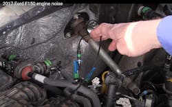
Using an oscilloscope to properly diagnose engine noise

Many shops may have problems when diagnosing a vehicle if they don't realize that there are advanced diagnostic solutions for some of these issues. One such example is when looking for engine noise. Many times, engine noises can be quite difficult for a shop to properly diagnose. Here is an advanced method that will be more accurate when diagnosing engine noise. This method will utilize an oscilloscope to sync the engine noise to the engine events using multiple microphones.
Elusive engine noise
When an engine timing event (such as an ignition coil discharge) is used to synchronize with an engine noise, incorporating the use of multiple microphones can help a shop make an accurate diagnosis. The multiple microphones will be placed around the engine so that the origin of the sound emission can be determined. In our example, we have a 2017 Ford F-150 with a V6 3.5 liter engine (Figure 1). It has an engine knock present at idle; the microphone placement is illustrated in Figure 2.
The shop that originally diagnosed this noise actuated the cam phasers and found that when the bank #1 phaser was actuated the engine noise changed. The shop then installed new camshaft phasers and timing chains on this V-6. However, the noise was still present once the engine was reassembled.
Note that it is important to have the microphones placed around the engine at different locations (Figures 3 and 4). Once you get the data, you may then need to move some of the microphones to different locations to pinpoint the origin of the noise within the engine.
An ignition coil will be used to sync the noise event to the engine. In our example, the #2 coil is used. To determine which ignition coil event to use, all the ignition coils were unplugged one at a time. When cylinder #2 was unplugged, there was a change in the noise of the engine as the engine knock doubled (Figure 5).
- Yellow — Ignition coil sync from coil #2
- Red — Microphone from bank #1
- Green — Microphone from bank #2
- Blue — Microphone at the front engine cover
Now let’s analyze this data. The first thing we will need to do is to mark the engine events with an overlay. In this case when the Mark Camshaft button on the scope is pushed it will mark these engine events with the pink partitions that are spread over the data from ignition trigger to ignition trigger (one full engine cycle) (Figure 5).
Now the strokes of the engine are indicted — intake, compression, power, exhaust. Notice that the red microphone waveform is bigger in amplitude (top to bottom) than the green or blue microphone waveform readings. This indicates that the noise is being created on bank #1. Now, look at where in time the noise is present. Concerning the engine events, the noise is present on the power stroke and the intake stroke. So what do these strokes have in common? Both of these strokes have the piston moving downward and are, therefore, unloaded. In my experience, when the noise is present on the downward stroke of the engine this usually indicates there is a problem with the piston or piston pin.
Dodging the silver bullet
So the next step would be to remove the spark plug and use a borescope to check the #2 cylinder. Figure 6 shows the inside of cylinder #2. Now it can be seen that the piston pin is loose and has been rubbing the cylinder wall within the cylinder. This engine will need to be disassembled and rebored to be repaired.
This is a far cry from the camshaft phasers and timing chains. It is better to run accurate tests and use the data than to rely on a known problem with a system (or what’s commonly referred to as a “silver bullet”). Many Ford engines have a known noise issue with the camshaft phasers. When the shop actuated the camshaft phaser, the #2 cylinder started to misfire causing the engine noise to change by unloading the piston. This was the cause of the misdiagnosis.
Be very careful when changing a variable during your diagnostic process. Whether it is actuating a cam phaser or simply unplugging a sensor connector, the resulting change this sometimes creates within a system can be misleading, as can be seen on this Ford F-150.
About the Author
Bernie Thompson
Contributing Editor
Bernie Thompson is an accomplished automotive diagnostician and trainer, and is also the co-founder of Automotive Test Solutions (ATS) based in Albuquerque, New Mexico. He has over 40 years of experience in automotive gasoline and diesel repair. Over twenty years of experience in design, engineering, and fabrication of automotive diagnostic equipment. Mr. Thompson holds; 22 US patents, 1 European patent, 1 Canadian patent, with 22 U.S. patents pending, 3 European patents pending, and 3 Canadian patents pending. Additionally Mr. Thompson writes automotive training curriculum for the automotive industry, is an editorial contributor for Motor Magazine, Motor Age Magazine, and has co-authored an SAE paper. Thompson also teaches advanced automotive diagnostic curriculum internationally. Connect with Thompson on the ATS Facebook page.


