I’ll bet a lot of you are probably wondering why I am asking this question. Using a transducer in a surge tank or radiator of a cooling system has been in practice now for several years. However, when I was working on this bus, another technician came by and asked me this question exactly as the title states. The technician knew that the tool I was using was a transducer, but he was curious about what I was using it for. So as not to ruin the case study, let’s go ahead and start at the beginning and let me explain how this question of the transducer in the surge tank came about.
Boiling point
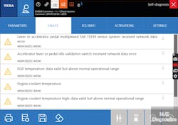
Late one afternoon, I was given a complaint card from a driver stating that the vehicle had a check engine light illuminated and it was showing high temperature on the gauge. I then go get my aftermarket scanner to check codes. The vehicle I am working on is a 2011 40 ft. New Flyer low floor bus with a Cummins ISL 9 Engine. I look at the codes and stored is below:
· 1515- which is for the Multiplex Accelerator Pedal
· 3527- which is for the Accelerator Pedal or Lever Idle Validation Switch
· 2962- Exhaust Gas Recirculation Temperature
· 2646- for Engine coolant temperature condition exists
· 2963- Engine Coolant Temperature Data Valid but above normal operating range least severe level
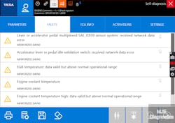
· 2961- Exhaust Gas Recirculation Temperature Data Valid but above normal operating range (Figures 1, 2)
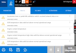
For now, I am not worried about the Accelerator Pedal DTCs. I am concerned about the symptom, the Engine is overheating. I then notice that the frequency of certain DTCs has more counts than others as (Figures 3, 4, 5). From my experience when you see this info you need to concentrate your efforts heavily on these codes and then see how they can relate to other codes. So, after seeing that the EGR codes were counting up the highest and, coolant temp codes were present as well I decided to graph some data with my scanner and go on a test drive. I wanted to see how the EGR and the Coolant Temp relate to each other.
Test drive
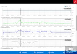
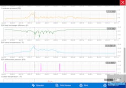
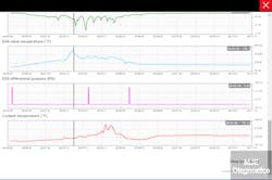
I get everything set to record on the scanner so I can pay attention to driving. I recommend to anyone using a scanner to graph data and record a movie of it so you can review it when you get back. I got back to the shop and reviewed the data and I notice a pattern (Figures 6, 7, 8). The crankcase pressure sensor signal voltage is at 2.88 Volts (which is 1.9 psi) under load at 1247 rpm. The EGR temperature sensor signal voltage is decreasing at the same time which indicates the EGR temperature is increasing (this sensor is a Negative Temperature Coefficient sensor). Another piece of information that gives us some insight here is the EGR Efficiency PID. It too is decreasing. There is also substantial increase in coolant temperature and momentary spikes in EGR differential pressure. So after seeing this data, I was convinced that there was a combustion leak somewhere on the engine but, where?
How am I going to prove it?
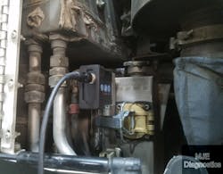
So here is how I am going to prove it as mentioned in the title. A transducer in the surge tank. As shown here (Figure 9), I have inserted a transducer into the surge tank of this bus to prove where the combustion pressure is coming from. I have also put a low amp clamp on Injector no 1 for my synch. The reason I did this is to see if the pressure increase has any relationship to the firing order of the engine.
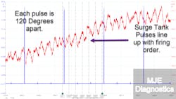
After doing the third capture, I saw a repetitive pattern (Figure 10). Each time there is a pressure rise in the surge tank it correlates with the firing order of the engine. Figure 11 shows the degree rulers being shifted to the left and proves they line right up with the firing of each cylinder (which is 120 degrees apart for an inline 6-cylinder engine). I now had the proof I needed to confirm a bad part. So, before I give away the answer let's think about the data, what type of engine this is, and what the scope is telling us.
I have proved without a shadow of a doubt that a combustion leak is present. But we still have the question of where it’s coming from? It can’t be from a faulty air compressor on this engine because the air compressor has two cylinders on it, and the pulses wouldn’t have correlated with the cylinders’ firing events. There would only be two distinct exhaust pulses if one were scoping the air compressor at its outlet line. This engine has EGR with a DPF as well as an SCR and is a high-pressure common rail fueling system. Remember in the scan data that the EGR temperature was increasing and the efficiency PID was decreasing? Plus, the crankcase pressure was increasing. We know it cannot be a base engine combustion leak because of the waveform present. There are pressure pulses representative of each cylinders’ combustion event. What is one common component of this engine that could cause pressure pulses to be exhibited for each cylinder? The EGR cooler. The EGR cooler was leaking and pushing the exhaust gases of the entire engine into the cooling system. I was able to determine this by using a transducer.
This was just another example of diagnostic techniques from the automotive side that can also be utilized in the heavy-duty world. Automotive Techs have been using this technique for a long time. We replaced the EGR Cooler and took it for a test drive and had no more codes, as indicated in Figure 12. Another thing I would like to add is the vehicle was diagnosed with an aftermarket scan tool. Having OEM tools are nice, but you can still fix a lot of vehicles with aftermarket equipment. It certainly is a feasible option compared to OEM and all the subscriptions you must keep up with.
About the Author

Michael Eilbracht
Michael Eilbracht is a transit bus technician for the Champaign and Urbana Mass Transit District in Urbana, Ill., and is the owner of MJE Diagnostics, a heavy-duty mobile diagnostic and training business. He is also an ASE Certified Master Transit Bus Technician and also holds an Advanced L2 Certification.
