Body electrical operation and testing

Modern body electrical systems no longer resemble the simple switched circuits technicians grew up diagnosing. Windows, mirrors, wipers and lighting functions are now controlled by multiple modules communicating across vehicle networks. Understanding how these systems operate, and how to approach them diagnostically, is essential for reducing diagnostic time and avoiding unnecessary component replacement.
This technical focus looks at body control functions through real-world examples, highlighting how a scan-tool-led approach transforms fault-finding on modern vehicles.
Traditional body electrical diagnosis
On older vehicles, body electrical circuits were relatively straightforward. Take a 2001 Chevrolet Tahoe rear window motor as an example.
Typical circuit elements included:
- Power supply
- Ground
- Relay
- Mechanical switch
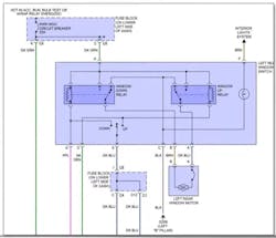
With so few components involved, fault-finding is focused on checking continuity, voltage supply and switch operation. Although trim removal could be time-consuming, the diagnostic logic is simple and linear.
How modern body control systems operate
Fast forward to newer vehicles and the same function becomes significantly more complex. On a 2016 Chevrolet Tahoe, the left rear window switch is no longer just a switch, it is a module.
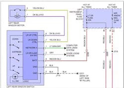
In addition to power and ground, the switch is connected to:
- Computer data lines
- Door lock systems
- A local logic board
Commands are transmitted over the local interconnect network (LIN) bus, with the module interpreting data messages that determine window operation. On this platform, there are four separate LIN buses. The rear window switch operates on LIN Bus 4, a 12V single-wire network. When viewed on a scope, this produces a square-wave signal with a constantly changing data pattern.
Integrated motor and logic modules
Some vehicles go a step further. On the 2016 Cadillac Escalade, the motor, switch logic and control electronics are integrated into a single assembly.
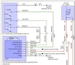
The physical switch inputs are processed locally, and the module then sends data signals, such as door ajar status across the network. While the exterior function appears familiar, the internal operation is entirely different. This is why applying older diagnostic habits to modern body systems often leads to wasted time and incorrect conclusions.
Changing the diagnostic mindset
Modern body control diagnosis starts with understanding inputs, outputs and data flow rather than chasing wires.
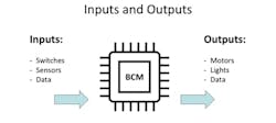
Body control module overview
Common inputs include:
- Switches
- Sensors
- Vehicle data (speed signals, transmission range inputs)
Common outputs include:
- Motors (windows, wipers)
- Lighting circuits
- Network voltages and control signals
The module processes inputs, makes logic-based decisions, and commands outputs — often across networks rather than direct wiring.
Case study: 2011 Jeep Liberty rear wiper

Customer complaint: Rear wiper inoperative
At first glance, this could involve:
- A failed motor
- A faulty switch
- Wiring damage
- Module failure
A traditional diagnosis might involve removing trim panels and chasing wiring — a time-consuming process with no guarantee of a quick answer.
Step 1: Pre-scan the vehicle
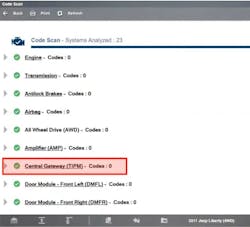
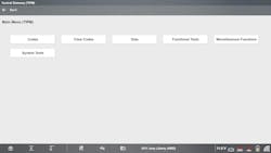
Begin with a full vehicle pre-scan. In this case, no diagnostic trouble codes were present. Next, access the central gateway / totally integrated power module (TIPM).
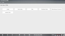
Step 2: Use functional tests
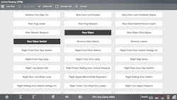
Navigate to: Functional Tests → Rear Wiper
From here, the rear wiper can be commanded ON or OFF directly from the scan tool.
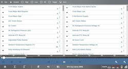
To simplify analysis, use the custom data list feature:
- Deselect all parameters
- Select only rear wiper and rear wiper switch

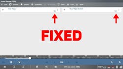
Verify the output side
Return to list view. Below you’ll see just the rear wiper and rear wiper switch. Simply toggle the on /off functions and you’ll see the ON/OFF status of both the rear wiper and the rear wiper switch. Then confirm visually that the rear wiper is wiping.
Using the functional test to turn on the rear wiper, we have verified that half of the circuit is working. This is good news, as now we know that everything between the TIPM to the motor is working when it is commanded from the scan tool, therefore there is no need to check the motor, chase the wires on the harness or verify the output of the TIPM is functioning. In about a minute, we’ve verified that one half of the system is operating as intended and already saved a ton of time.
Step 4: Verify the input side
We can now check the data stream to verify the input side of the circuit.

From here, if we turn the rear wiper switch within the vehicle and nothing happens, as in this case the tool display is off for both the rear wiper and the rear wiper switch, then we know that the module does not see the wiper switch.
Possible issues could be the switch, the wiring or the BCM, but now we know where to look. Checking the data helps to verify the input side. In this case, the TIPM is not receiving a signal from the switch. Upon further investigation the switch was found to be bad and the switch was replaced.
Step 5: Confirm the repair
After replacing the switch:
- Operate the switch again
- Observe correct ON/OFF status in data
- Confirm rear wiper operation visually
This confirms correct system operation without unnecessary component testing. Verifying inputs and outputs using your scan tool will save a ton of time removing panels, chasing wires, etc.
Module replacement: Coding and relearn procedures
The Jeep Liberty case study highlights how verifying inputs and outputs can quickly isolate faults. However, it also reinforces a wider point: many body control modules will not function correctly after replacement until coding or relearn procedures are completed. Modern vehicles store configuration data within body modules to match the vehicle’s equipment level, network layout and comfort features. When a module is replaced, this information is often missing or incorrect, leading to partial or complete loss of functionality.
Common body modules that may require coding or relearn
Depending on the vehicle, this can include:
- Door modules and window regulators
- Mirror control modules
- Steering column and steering rack modules
- Lighting and headlamp control units
- Tailgate, trunk, and power liftgate modules
Without completing the correct post-installation procedure, symptoms can range from inoperative features to network communication faults.
Conclusion
Body electrical faults no longer need to involve hours of trim removal and wiring checks. By understanding how modern body control systems operate, and using scan tool data and functional tests effectively, techs can isolate faults quickly and confidently.
Explore the body electrical functions and guided component tests within your Snap-on® diagnostic platform to streamline diagnostics and reduce vehicle downtime.
For more on this topic, click here.