Content brought to you by Motor Age. To subscribe, click here.
What You Will Learn:
• Fundamentals are the basis for sound diagnostic skills
• Important data can be found service information sources, streamlining the diagnostic process
• Always followed the test results to determine where to test next
2014 Lexus GS350
112,246 miles
3.5L V-6
RWD Automatic
Complaint: "Crank/no-start after the vehicle collided with a snowbank"
We often encounter a vehicle or system we are unfamiliar with. But it's not our familiarity that allows for efficiency and accuracy. It's the solid base of knowledge we've developed that does so.
Think about this question: How many times have you relied on someone else to fix a fundamental problem? If you say never, I am glad, but I must encourage you to accept the reality of our industry. I have a limited reservation in asking others in the field for assistance when performing services or diagnostics with which I lack familiarity. Open communication in this field is extremely important and creates professional growth to assist both individual and communal performance.
In the instance of this case, an overly apparent fault created confusion for the technician assigned to this vehicle. As a result, I acted as his resource to successfully understand, diagnose, and repair the vehicle. I feel obligated to assist those who ask me for assistance in odd instances and use these experiences to justify my professional occupation by developing presentable cases for implementation in future course materials.
A broad variety of technicians practice in the automotive service industry. Sometimes they fall into a world of crude mechanical work and are content. Others may explore the most advanced technologies with personalized understanding and still be hungry for more. As a technician educator, it is my job and passion to prepare anyone who walks into our doors for the broad array of service occupations our industry offers. I cannot guarantee what the students learn (in a brief 1-2 years of study) will be beneficial if they do not see the opportunity the industry provides when they exit. I also cannot guarantee my students (upon graduation) will be provided the opportunity to explore service and/or diagnostic methods that enhance their previous learning experiences in academia. This is one of the many reasons I find myself assisting others in diagnosing problems that seem complicated but are found to be extremely fundamental (Figure 1).
Case in point: I was asked to help a technician/former student in our region analyze a 112,000-mile 2014 Lexus GS350 Sedan. It had a complaint of no start. To be more specific, this only happened after our most recent snowstorm (STL Metro region) encouraged snow to inconveniently make its way into the under-hood area of the vehicle while the driver was operating it, in early 2022.
This vehicle was towed to the technician's residence and sat for two days before I was able to assist. I had a few questions related to the vehicle's service history, symptoms experienced, and if visible damage was present. I also inquired about services performed since the technician received the vehicle. The vehicle was a recent auction purchase, had 5 of 6 spark plugs replaced, a new battery installed, and a MIL illuminated.
As basic as it may seem, I consistently apply the following critical steps when diagnosing faults with a driveability or emissions concern:
Step 1: Verifying the complaint
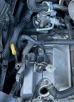
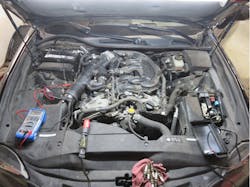
This process is sensory and relies on physical interaction with the vehicle. To verify this complaint, I cranked the engine over and verified a “crank, no-start” was truly present. Oftentimes, conducting a visual inspection can provide focused results, as was the case in this instance. In observing non-OEM wiring attached to ignition coil #1’s factory harness, I developed an immediate concern that the ignition system’s obvious alteration may be related to the present no-start condition.
Step 2: Gathering DTCs
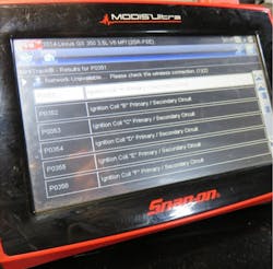
Gathering DTCs is a valid practice that enhances our experience as technicians. Considering the multi-modality of OBD-II, it is extremely important to understand how issues identified by control modules are captured, stored, and then reported as faults that impact critical systems of operation in engine controls. DTC's P0351-P0356 were found in the PCM of this Lexus. These DTCs are described loosely as "Ignition A-F Primary/Secondary Circuit".
Step 3: Reviewing service information for platform fault commonalities
While it was not likely that TSBs nor recalls were going to quickly identify the fault conditions on this vehicle, technicians must be aware that both pieces found within service information are oftentimes critical for success. TSBs are generated by OEMs in response to frequently identified failures uncovered by technicians that act as a resource during terms of warranty coverage (and beyond). These are shared to reduce the time invested for diagnostic and service procedures to resolve sometimes confusing or unfamiliar system complaints and/or conditions.
On the other hand, recalls are implemented in response to emissions control and/or vehicle safety concerns. Both are excellent resources to review in the instance a driveability, emissions, or safety concern is provided by the consumer. In the case of the Lexus, zero campaigns were listed related to the presence of common ignition circuit DTCs.
Step 3: Dissecting the DTCs
Reviewing service information to find conditions for running and setting the DTCs is a necessary step to understanding what conditions objectively encourage fault presence in stored data. For P0351-P0356 to be identified and stored is solely a result of the PCM not receiving "IGF" signals while the engine is running. As I wasn't extremely familiar with Toyota/Lexus' common ignition control systems, I used the next step to provide myself and the technician with an understanding of this system (Figure 2).
Step 4: Understanding the system of concern
Collecting diagrams, procedures, and illustrative service information act as a major resource in the understanding system(s) or component theory. In reviewing the diagnostic sequence for the present DTCs, I found Toyota/Lexus to provide a clean, descriptive summary of their ignition controls that included illustrations, diagrams, measurable values, and sequence of operation.
From a broad perspective, this Lexus ignition system uses critical parts for ignition control such as CKP, VVT, a diverse array of other fundamental inputs (i.e., ECT, TPS), the PCM, the vehicle’s power/ground source, and 6 coils (loads) for successful ignition. As this array of parts can seem intimidating in the diagnostic process, it provides major points of data and/or measurement to build a valid procedure.
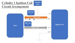
In a summative perspective, each ignition coil must be provided switched B+, constant ground, an ignition trigger signal (IGT) from the PCM and output a feedback signal (IGF) to verify operation as a way to satisfy the PCM. Essentially, the PCM wants to know if the request for ignition was honored by the coil. Service information provided some specified values for B+, IGT, IGF, and ground measurements. IGF and IGT values were inferred based on OEM-provided waveforms found in service information (Figure 3).
Step 5: Gathering Measurable Data and Inferring Faults
As noted in service information, KOEO/KOER, B+ must be provided to terminal 1. The OEM noted that to test the terminal 4 ground circuit (Key OFF), utilize a DMM's Ohmic setting to measure live resistance between terminal 4 and body ground with the ignition coil disconnected. The specified resistance value is less than 1 Ohm.
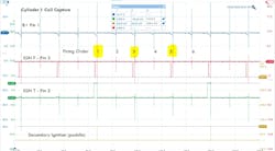
In KOER, the IGT (trigger terminal of the ignition coil) is received from the vehicle's ECM to communicate primary charge/secondary output requests and IGF (feedback) verifies the request from the PCM was internally honored by the Ignition Coil assembly. The IGT signal is unique to each coil on this vehicle in that it is only shared with the ECM. It is pulsed high (~4V) and rests at 0V. When IGT drops low to 0V, secondary ignition occurs.
The IGF, however, is shared amongst 3 cylinders per bank, therefore labeled as IGF1 and IGF2. The IGF is pulled low from ~5V to ~.5V to let the ECM know the trigger request has been honored. IGF1 is linked to cylinders 1,3, and 5 on the passenger side bank, while IGF2 is linked to cylinders 2,4,6 on the driver side bank. Service information provided all the necessary information to understand the sequence of operation.
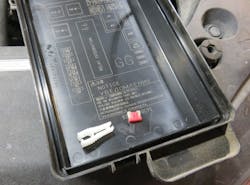
Now knowing how the circuit operates, I concluded ignition coil 1 would be the most convenient and effective point to measure voltage and continuity based on location. When measuring voltage during a crank request at terminal 1 of coil 1, I immediately found 0V present. This came as no surprise due to the unexplainable piece of wire crudely tapped into coil 1’s power supply circuit, which was contacting body ground. We immediately removed this non-original wire from the harness to eliminate any further damage it could cause. Using the circuit diagram, I located the 10A ignition fuse common to all ignition coils and found it open (Figure 4+5).
Finding this visible problem created a few basic questions:
- Do I just replace the fuse?
- What tools can I use to quickly isolate the reason(s) beyond the obvious about its fault?
To prevent potential future damage, I placed the IPA Fuse Saver in the IGN fuse slot with a breaker rated at 10A. In performing a wiggle test, the breaker did not trip, indicating the immediate fault of a short-to-ground was absent. I have used this tool for nearly a decade to reduce my cost in diagnosing higher amperage circuit faults (i.e., preventing the commonly blown fuses in circuit diagnosis). The Fuse Saver tool is equipped with multiple current limiting circuit breakers (ratings). I also purchased this kit with a BuzzAlert, which creates an audible output if the installed breaker trips while connected to the main circuit (Figure 6).
Step 6: Repair and Verification
After locating the obvious short-to-ground fault, I had the technician remove the non-OEM wires and then repair and seal the harness. In wanting to verify our routine was valid, I then wanted to collect raw data using an oscilloscope to witness normalized operation for future reference (Figure 7).
We connected a Pico 4425A to ignition coil 1's terminals:
- Channel A was linked to Terminal 1 to measure live and active load voltage
- Channel B was connected to terminal 2 to collect IGF output
- Channel C was connected to terminal 3 for IGT output
- Channel D was connected to a secondary paddle probe to collect an illustrative capture that proved both theory and assumptions were reasonable.
If the technician I assisted in this diagnostic process encounters Toyota/Lexus vehicles of the same era with this ignition system, I am comfortable in knowing his experience from this case study will guide him down a more structured diagnostic path. Sharing our knowledge of circuit theory, methods of measurement, navigating service information, and capturing live data provided an objective conclusion for this fault. Simply asking for assistance provided this young technician with experience in using basic information and will hopefully assist him in future diagnoses.
About the Author
Chris Reynolds
Chris Reynolds is an ASE Master Technician, ASE-Education Foundation evaluation team leader, and an associate professor of automotive technology at Lewis & Clark Community College in Godfrey, Illinois. He is currently in his second year of study toward a Doctor of Education in Educational Practice degree at the University of Missouri – St. Louis. He enjoys time with his wife and three children and advocating for the needs of the automotive service industry and the field of technical education.

