Conquering an intermittent MIL illumination on a Chrysler Concorde
Content brought to you by Motor Age. To subscribe, click here.
What You Will Learn:
• Follow the facts until you get to the answer
• Let the results of the easy tests determine where to conduct more involved testing
• A lab scope allows you to see how different circuits relate and can make problem-solving much easier
The confidence that grows and is felt within a technician after things begin to "click" is indescribable. Honestly, it's a bit addicting, and I'll be the first to admit it. You've probably heard me say this many times in the past, but after gaining a thorough understanding, diagnostic work feels less like work and more like a game. With that said, I’m sure many of you diagnosticians will agree that you’d rather do diagnostic work than any other type of work that is taking place throughout the shop on any given day.
This might sound a bit insane but, the only thing I enjoy more than diagnostic work is when a job kicks my butt!
Why? Because that is the opportunity to become a better, more well-rounded, and clever technician. This is exactly what my great friend and fellow Trained By Tech, Brian Culotta (of Dave’s Auto Care in Willoughby, Ohio) experienced in this saga below.
Overfed and underperforming
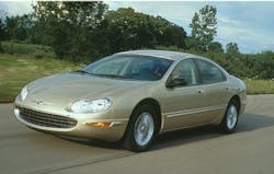
The day began with a 2004 Chrysler Concorde 2.7L (Figure 1). The vehicle was recently purchased, and the customer brought it to the shop with the complaint that the MIL illuminates erratically. The vehicle will need to pass an emissions test, as required by the state. The fault must be rectified to get the vehicle back on the road legally.
A scan for DTCs was performed, but when the scan tool attempted to identify the vehicle at the DLC, the process failed. The PCM even failed to communicate when the vehicle was built within the scan tool manually. A different scan tool was used, and the same attempts were made. No communication could be established in the enhanced-data side of the PCM. However, access to the PCM data was granted when an attempt was made on the generic OBD2 side of the PCM. There, a DTC P0172- “Fuel system too rich, Bank 2” was stored.
Brian had a conversation with the customer, and it was stated that the vehicle had previous work performed elsewhere but the customer didn’t know what work was performed or the reason why. Brian began to evaluate the vehicle preliminarily and found the following items to have appeared to be “new.” It is indeed a long list of parts. Surely, a lot of time and money was invested. Who's to say it didn't need all of those parts replaced? We know the chances are very slim though.
Crankshaft position sensor
Camshaft position sensor
Throttle position sensor
Three ignition coils
Six spark plugs
Idle air control motor
Map sensor
Both upstream HO2 sensors
Brian proceeded with his detective work and began to analyze some live scan tool data. It’s always worth the time to begin in the driver’s seat with drivability faults. So much can be revealed with so little effort.
The total fuel trim (for both banks) indicated the PCM was taking away 10 percent of fuel. This number stayed true under almost all operating conditions (in the work bay and on the road). The vehicle seemed to be operating without any symptoms at that time. After some time, more DTCs were stored and these included P0300- “Random misfire” as well as P0301- “Cylinder #1 misfire.”
When back at the workshop, the vehicle was restarted and was running very poorly. Brian noted the pungent exhaust fumes to be a bit overwhelming. Scan data was once again reviewed and the total fuel trim for bank #1 was -50 percent. Bank #2 was also having to reduce fuel delivery but only with a -15 percent total fuel trim correction. At this time, a noticeable misfire(s) was present. Brian’s thought was that the misfire was the result of the rich-condition and what the PCM was attempting to correct for.
Diagnostic dizziness
Brian decided it would be time well spent pursuing the misfire. He figured the result of both symptoms would be discovered this way. He knew that a misfire is only caused by one of three conditions:
- Inadequate or improperly timed spark
- Compromised cylinder integrity or ability to pump air
- Improper fuel delivery
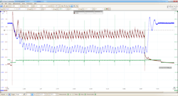
Thus, Brian began his evaluation with the easiest test to perform (I’m with him on this one). He chose to perform a relative compression test. On a lab scope, capturing the starter motor current and plotting it over time, it could be seen how each cylinder loads the starter mechanically. The harder the starter has to work, the more current it will consume. This is an easy way to infer if one or more cylinders is lacking in compression. Because Brian is using a multi-trace lab scope, he chose to add other traces to the capture to yield even more information with little added effort (like fishing with a net, instead of a pole). He used an ignition strike from coil #1 and sampled intake manifold pressure with a pressure transducer (Figure 2). If a cylinder was compromised, the pressure transducer data could alert him to where the leak may be. This is such a time-saver when you practice the technique and become familiar with it. Combined, the lab scope capture will serve as a “Go/No-Go” for an engine mechanical fault.
- BLUE= intake manifold pressure
- RED= Starter Amperage
- GREEN= #1 ignition strike
What was noticed in the captures led Brian away from an engine mechanical fault. Although three of the six cylinders' amperage peaks were relatively lower in amplitude, it's likely caused by "fuel wash" from the overly rich condition. Meaning, the loss of compression was a result of the problem, not the cause.
Shortly after this test was performed, Brian thought it best to perform some more easy tests, as he still had no diagnostic direction. Although it appears to be an overly rich fueling concern, the underlying fault had not yet been revealed; therefore, Brian struggled to find a sense of direction. He realized that it is not prudent to perform random tests, as it just wastes time. Perhaps another easy test may give him the sense of direction needed to pursue the fault efficiently and with confidence. Brian attempted to capture and analyze ignition waveforms. This would have given him a live view of the combustion events occurring within the cylinder without any disassembly. Unfortunately, the vehicle doesn’t want to play nice. Once the engine was started it ran great with no fuel trim correction, which was very frustrating, and all the more reason Brian needed a diagnostic direction before going any further.
After almost two hours of rest, the engine was restarted, and the fault was still in remission. Having no other choice, Brian decided it was best to inspect the newly installed components. He removed the spark plugs and found two of them to be extremely sooty (Figure 3). This was to be expected, as the PCM was attempting to correct for an extremely rich condition. The plugs were reinstalled, and the vehicle sat overnight with the hope that the fault will be exhibited in the morning and further testing can be conducted.
A second go-round
Upon the cold morning start-up, the engine misfired heavily once again. As before, the exhaust fumes were very potent, indicating the overabundance of fuel that matched the evidence left on the spark plugs the day before. Brian noticed that this fault only seems to occur when the vehicle is very cold, and the customer concurred.
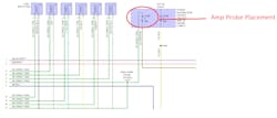
The scan tool was again interfaced, and the fuel trims were viewed. Bank #1 -50 percent and bank #2 -15 percent total fuel trim. Unable to get the picture from his mind, Brian recalled the sooty #3 and #5 spark plugs (the “result” of the problem). He thought this to be the best area to focus his testing, in hope of leading him to the root-cause. First focusing his attention on the wiring diagram, it was determined he could obtain the current flow for the ignition coils and fuel injectors simultaneously with just one amp probe (Figure 4). Brian then decided to use the lab scope and monitor the injector activity to see the reason for the carbon-fouled spark plugs.
Brian interfaced the lab scope, his amp probe and allowed the vehicle to cool for an hour, as he waited patiently. He started the engine, and the vehicle exhibited the rough-running condition. Brian captured the data for a few seconds and retreated to his workstation and viewed his PC (Figure 5).
There were a few strange characteristics of the captured lab scope data. First, the blue trace is derived from the amp probe, capturing current follows for all six ignition coil primary circuits and all six fuel injectors. The tall portion of the ramps is from current flowing through the ignition coils as they dwell. The smaller portion of the ramps occurs as the coil dwell ceases and the fuel injector is energized. Cycle after cycle, two of the injector amperage ramps displayed an unusually high amplitude. What’s more is that the sequentially fired fuel injection system should allow the injectors to fire, in-turn and individually. It appears that two of the injectors are firing in tandem and repeatedly for two back-to-back events (GREEN and YELLOW). The strange-looking amperage ramps are a result of the fuel injector circuits' erratic operation. It now makes sense why the spark plugs for cylinders #3 and #5 are particularly sooty. The cylinders they are assigned to are getting a double-dose of fuel for each engine cycle.
Perhaps this is a PCM mis-triggering issue
Perhaps the CKP or CMP signals contain a glitch and causing a strange PCM-reset symptom
Could there be a board-issue allowing two injector driver circuits to short together (seen this many times on older Toyota/Lexus vehicles)?
These are the thoughts that surface after analyzing the captured data. These are very valid questions and what diagnostics is all about — asking “why?” and getting to the root cause of the fault/symptom.
The ins and outs of computer control
In case it wasn’t obvious, it is worth mentioning: Computers are not smart by any means. They serve a purpose and that is to compute very swiftly and have a precisely controlled output. They simply do what they are programmed to do. They receive inputs, process the data, and create a resulting output. If the inputs are no good, so too will the outputs. What I'm getting at is that Brian cannot fault a PCM for creating a bad output (Fuel injector circuit control) without first verifying it has what it needs to make a proper decision.
The focus now is on the inputs. Although new, the CKP and CMP sensor signal circuits were tested for integrity at the PCM connector. While there, Brian decided to also inspect the two suspect fuel injector circuits. After all, if they were somehow shorted together (within the engine harness) it would surely cause the same lab scope captures, as well as the experienced symptoms.
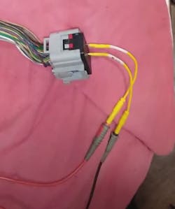
With the PCM and injectors disconnected, the injector control circuits were isolated from the rest of the vehicle and each other. The leads from a DVOM were connected to both injector control circuits (Figure 6). The meter displayed continuity, proving both the #3 fuel injector control circuit and #5 fuel injector control circuit to be shorted together. This logical thought process allowed Brian’s test result to drive his diagnostic approach. The hunt is now on!
The point is the rest of the fuel injector control harness is located beneath the intake manifold plenum and is inaccessible (Figure 7). The previous test for continuity justifies the removal of the plenum because the fault will indeed be discovered there. Brian’s suspicions and the result of the previously performed tests were confirmed visually. The insulation had fallen off the wires and was the cause of the shorted injector circuits (Figure 8). The wiring was repaired, and the vehicle functioned well thereafter. Two weeks had passed, and the customer called to confirm the vehicle continued to run well.
Training is a career-long endeavor
As time goes by and a diagnostic technician gains experience, his/her testing techniques become polished and more efficient. This is just a natural progression. On occasion though, we are faced with a problem vehicle that challenges our mind and our emotions. It is easy to get frustrated and anxious to move on from the vehicle to something else (another easier challenge that restores our confidence. I know because I have been there many times). I urge you to take these moments of self-doubt and frustration and embrace them.
It's these types of challenges we encounter so rarely that truly takes us to the next level. Step back and see the system you are faced with from a bird’s-eye view. Monitor and visualize how the inputs provide the necessary data for the ECU's decision-making. Monitor the outputs and how they function.
This will allow you to verify the circuits’ integrity but also the ECU’s ability to properly process the inputs and create the output.
Every system functions very similarly from that aspect (inputs/processing/outputs). It's just "computer-control." Think about the possibilities, prove what simply cannot be, and focus your testing on what remains. Don't stop asking "WHY" until you've reached the root cause of the fault! Although it takes time and patience, the dividends yielded will pay you for decades to come If you’ll simply let it.
About the Author
Brandon Steckler
Technical Editor | Motor Age
Brandon began his career in Northampton County Community College in Bethlehem, Pennsylvania, where he was a student of GM’s Automotive Service Educational program. In 2001, he graduated top of his class and earned the GM Leadership award for his efforts. He later began working as a technician at a Saturn dealership in Reading, Pennsylvania, where he quickly attained Master Technician status. He later transitioned to working with Hondas, where he aggressively worked to attain another Master Technician status.
Always having a passion for a full understanding of system/component functionality, he rapidly earned a reputation for deciphering strange failures at an efficient pace and became known as an information specialist among the staff and peers at the dealership. In search of new challenges, he transitioned away from the dealership and to the independent world, where he specialized in diagnostics and driveability.
Today, he is an instructor with both Carquest Technical Institute and Worldpac Training Institute. Along with beta testing for Automotive Test Solutions, he develops curriculum/submits case studies for educational purposes. Through Steckler Automotive Technical Services, LLC., Brandon also provides telephone and live technical support, as well as private training, for technicians all across the world.
Brandon holds ASE certifications A1-A9 as well as C1 (Service Consultant). He is certified as an Advanced Level Specialist in L1 (Advanced Engine Performance), L2 (Advanced Diesel Engine Performance), L3 (Hybrid/EV Specialist), L4 (ADAS) and xEV-Level 2 (Technician electrical safety).
He contributes weekly to Facebook automotive chat groups, has authored several books and classes, and truly enjoys traveling across the globe to help other technicians attain a level of understanding that will serve them well throughout their careers.


