Network communications in modern vehicles
Discussion points
- Historical context: From simple wiring to early networks
- Current state: CAN, LIN, and gateway modules
- Diagnostics: The importance of electrical system fundamentals
- Network congestion: Challenges of expanding modules
- Current & future trends: Ethernet, LVDS, and faster protocols
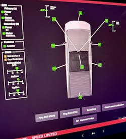
In my opinion, the automotive technology found in today’s modern automobiles is nothing short of amazing. Today, in-service technicians face complex vehicle communication systems that are not only crucial for proper and safe vehicle operation but can also aid the technician during troubleshooting by bringing them critical vehicle telemetry right to the built-in center stack within the vehicle. (Figure 1)
Today’s networks integrate dozens of electronic controllers managing sensor data, video data, and carrying out vehicle operations via actuators and other devices in a timely manner. Many of today’s vehicles utilize high-speed Ethernet and other protocols such as LVDS (low-voltage differential signaling) to support safety and driver assistance. There is no doubt in my mind that service personnel possessing the skills and knowledge needed to diagnose communication faults will be on the rise and will become a critical asset for any modern service facility. Mastering these systems requires a solid foundation in basic electrical skills and Ohm’s Law, as these fundamentals remain critical for troubleshooting even the most advanced networks. This article explores the past, present, and future of vehicle network communications, emphasizing diagnostic strategies, gateway modules, and how the challenges of network data congestion are driving new protocols and expansion buses.
Historical context: From simple wiring to early networks
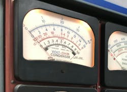
I started my professional career in the early 1980s, when vehicles relied on point-to-point wiring, with minimal electronics controlling basic functions such as ignition and lighting. Diagnosing vehicle anomalies primarily meant testing circuits with a test light and, in some cases, a multimeter. I remember attending classes discussing a new need for a meter that had 10 million ohms of impedance when testing low voltage sensor circuits, and without a solid understanding of Ohm’s Law (V=IR), many failed to understand why a typical large analog meter (Figure 2) was unacceptable for such tasks.
Additionally, most vehicle manufacturers weren’t too concerned about wiring mass. I remember servicing GM vehicles from the late 70s that had an orange diagnostic port under the hood, which was a diagnostic gang plug that tapped into several circuits designed to help the technician diagnose vehicle problems. If you needed to drive the starter, test the A/C compressor, tap ignition coil negative, lighting circuits, and others, this connector provided quick access.
In the early 80s, General Motors had introduced their computer controls, which really sparked my interest since almost all the seasoned techs around me didn’t want anything to do with these systems. One of my early scan tools was the MPSI Multi-Scanner (Figure 3), which read out serial data and provided the ability to issue commands back into the vehicle.
Bosch introduced the controller area network concept in the late 1980s, which was a significant technology shift that proposed allowing ECUs to share data over a communication bus, reducing wiring complexity. If you were working on European vehicles in the 90s, you likely were exposed to CAN, but for the rest of us, CAN was mandated around 2008 for OBD-II. In the late 1990s, Mercedes used HSCAN operating at 500 Kbps running powertrain controls.
Technicians adapted to scan tools but relied on electrical knowledge, along with wiring diagram interpretation skills, to diagnose circuit problems. This period provided the groundwork for today’s networks, reinforcing the strong need for technicians to possess basic electrical skills and knowledge to support efficient troubleshooting operations.
Current state: CAN, LIN, fiber, and gateway modules
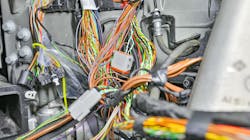
Today’s vehicles use multiple networks (Figure 4), with CAN, Ethernet, and others handling critical systems like powertrain controls and advanced driver assistance systems (ADAS) supporting numerous, extremely time-critical, safety functions. Lower speed systems may consist of either a twisted pair or single wire (SWCAN, LIN) to manage low-speed convenience functions such as seats, windows, and other non-critical items.
Gateway modules were introduced to allow messages traveling on different networks to be shared. For example, a gateway might translate CAN data from the engine, such as vehicle speed, to LIN for interior controls to automatically lock the doors at a programmed speed threshold. Gateways also enhance security by providing a physical or software-driven firewall to filter unauthorized access, prevent improper service operations, and/or provide traceability. For example, a carmaker may want to track when a vehicle receives ADAS service operations, such as a recalibration. They could require a 3rd party, such as Auto-Auth, to manage that access through credentialing, which could be logged within the vehicle and/or within external cloud-based storage systems.
Technicians must possess an understanding of gateway architecture to identify communication faults, whether these faults are due to software versioning, improper service functions, scan tool deficiencies, or electrical circuit faults. They will need the skills necessary to effectively deploy various tools such as DVOMs, oscilloscopes, network analyzers, specialized adapters, and more to interrogate the systems. When it comes to low-voltage systems, it is extremely crucial that the technician possesses foundational knowledge of Ohm’s Law and electronic circuit operational knowledge of transistors, diodes, MOSFETs, inductors, and other electronic components.
Diagnostics: The importance of electrical fundamentals
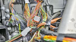
Diagnosing network issues demands more than scan tool proficiency, especially if the network(s) are down, leaving the scan tool unable to communicate with the vehicle. Faults in this category often stem from basic electrical circuit problems, such as unwanted resistance or circuit shorts to power, ground, or other network circuits. (Figure 5)
Unwanted resistance can come from corrosion and/or poor terminal fitment, which often stems from improper testing, i.e., using the wrong size male pin when testing female terminal sizes. However, I have seen replacement connectors come equipped with terminals not meeting the original terminal specifications. This is problematic because the initial install of the replacement connector may result in proper vehicle operation, but it’s only a matter of time before a fault surfaces. Additionally, the devices that get plugged into the J1962 OBD-II port, whether for diagnosis or other uses, can lead to problems down the road. Remember, each connector is rated for a limited number of cycles, and in addition to that, if the device used for interrogating the system has male pin sizes larger than specified, tool communication problems may arise down the road.
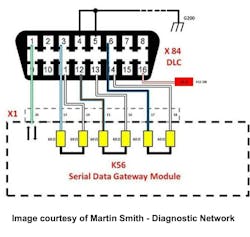
However, before any testing, the technician needs to baseline the system, meaning that they need to establish knowledge about the system configuration, wiring, termination, gateways, etc., and if they’re relying on older network knowledge, they are doing themselves a disservice. For example, for most HSCAN networks, we were taught that one method for checking network wiring integrity was to disconnect the battery and check the resistance across terminals 6 & 14 at the J1962 OBD-II port. If that test were conducted on newer GM vehicles equipped with a Serial Data Gateway Module (SDGM), they would undoubtedly observe 120 ohms of resistance. For a technician unfamiliar with this network architecture, translating those results into an actionable process to address would be in for a rough road ahead. As you can see in Figure 6, terminals 6 & 14 make a short run to the SDGM and are completely isolated from the other networks on the vehicle.
If you’re interested in learning more about GM network architecture, diagnostics, and other related topics, Martin Smith — one of my professional colleagues and a GM instructor — has posted numerous articles on the Diagnostic Network (diag.net). These articles can be extremely helpful for anyone seeking to further their knowledge on network diagnostics. See the sidebar for links to a few of these articles.
Corroded connectors, shorted wires, or improper grounds are some of the major problems technicians will typically face when troubleshooting network anomalies. As mentioned above, Ohm’s Law is crucial: a technician might measure resistance to detect an open circuit (infinite ohms) or measure low currents to learn if a module is powering up internally or if the module’s internal CAN transceivers are sending messages. For instance, a CAN bus requires 60 ohms of termination resistance, but the technician needs to have a solid understanding of the network's layout so they can leverage the terminating resistance. If they’re dealing with an intermittent communication problem — and have several connectors within that circuit — the technician will need to have the ability to test these circuits effectively during their diagnostic session. Using an ohmmeter might work, but this test is highly influenced by test lead and connection resistance. Using a milliohm meter with kelvin probes is one way to validate low-voltage signaling circuits by using higher currents and measuring true voltage drop at the probe tips, which eliminates influence on the measurements due to test lead resistance.
Electrical skills enable technicians to test power, ground, and signal lines methodically, avoiding guesswork. As networks gain complexities, these fundamentals remain the foundation of effective diagnostics, ensuring accurate fault isolation and, more importantly, getting to the root of the problem.
Network congestion: Challenges of expanding modules
Modern vehicles can have over 100 ECUs, from infotainment to ADAS, which share data on these networks. Given that there’s a limited number of messages that can be shared across a single network due to bandwidth limitations, manufacturers use expansion buses which can be classified as dedicated subnets for specific operations, like a separate CAN for chassis systems. Faster protocols like CAN FD (up to 8 Mbps) and Flex Ray (10 Mbps) reduce latency, but congestion persists. This drives adoption of high-bandwidth solutions like Ethernet (100 Mbps- 1GBit) and LVDS (2-20 Gbit) for high-speed, noise-resistant data transfer in applications like cameras delivering high bit-rate data. Technicians must understand these architectures to diagnose bottlenecks or protocol-specific faults.
Future trends: Ethernet, LVDS, and faster protocols
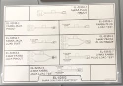
The future of vehicle network communications will involve high-speed networking protocols. Automotive Ethernet, with speeds up to 25 Gbps, supports data-intensive perception devices supporting autonomous driving systems. As mentioned earlier, some LVDS devices can be powered by the same circuit providing communication over coaxial cabling. You may have already seen such cabling where troubleshooting these systems will mostly involve testing the continuity of the cabling via specialized terminals and a high-resolution milliohmeter, as mentioned earlier. Repair steps for faulty cabling will usually result in an overlay cable since removing the old cabling would typically require extensive labor. To aid with testing these coaxial connections with common Fakra termination, there is a special tool kit that I have been using for the past 6-7 years. You may want to investigate acquiring it. (Figure 7)
Conclusion
As vehicle technology continues to evolve, this will push the technician to continually craft their skills around diagnostics, utilizing tools and techniques to advance their prowess. These skills will pay off as the software-defined vehicles (SDV) with zonal architectures begin to arrive in your bay. Additionally, the on-board diagnostics, remote access, and more will evolve as well, strengthening the diagnostic offerings embedded within the vehicle.
Expand your knowledge on network diagnostics with these articles from Martin Smith:
- GM Network Diagnostic Opportunities
- The Changing Face of CAN Bus Diagnostics on General Motors Vehicles
- GMLAN Diagnostics
Tools and equipment for modern vehicle network communication diagnostics:
About the Author

Scott Brown
Founder - Diagnostic Network
Scott is an ASE Master Certified Automobile Technician with L1, L3, & L4 credentials and has over 39 years of professional service industry experience. As an independent shop owner in Southern California and with his engagement at various levels of within our industry, he continuously strives to move the industry forward through networking, education, communications, and training. Scott is a founder of the Diagnostic Network (https://diag.net/) which was born in 2018 after he retired after 22 years at iATN, where he served as company president.
Brown is also the host of Professional Tool and Equipment News (PTEN) and VehicleServicePros.com podcast, Torque Factor. The podcast addresses the latest automotive service technologies while focusing on expanding knowledge and awareness around tools, equipment, education, and industry trends.
