Technician-induced diagnostic dilemmas
Content brought to you by Motor Age. To subscribe, click here.
What You Will Learn:
• Reference wiring diagrams before approaching the vehicle
• A scan tool used to check for communicating nodes will help triangulate the location of a network fault
• Great information can be found in both factory OEM wiring diagrams as well as aftermarket sources
I recently encountered two vehicles with technician-induced problems that I believe offer some valuable lessons. Whether we caused the problem or we’re there to diagnose it, rushing and jumping to conclusions often costs us more time in the end.
2013 Ford Focus-The customer brought in a 2013 Ford Focus for an intermittent no-crank condition.
My usual diagnostic routine is a pre-scan, a quick visual inspection, and an interview with either the shop owner I’m called to assist or the vehicle owner. But as usual, I got only part of the story, even after thorough questioning. I’ll never understand why this happens.
The shop tested the car and didn't find anything wrong, so it returned the vehicle to the customer. A week later, the vehicle returned to the shop on the hook of a tow truck. The customer stated that the vehicle had refused to start a few instances, and this time it had died on road. The technician at the shop approached the vehicle and it started right up. The tech believed the starter must be the culprit. This is not a logical direction to head in for a vehicle that suddenly died on the road.
The shop owner told me they installed a starter, lowered the vehicle to verify it started and then raised the vehicle to install the underbody shield. They then lowered the vehicle and it again failed to start. They tried to scan the vehicle and found it would not communicate. They decided to push the car out and give me a call.
Jumping the gun
I connected my Snap-on Zeus+ scan tool, and the first thing I noticed was the vehicle did not auto-identify with the scanner. I manually selected the vehicle and reestablished communication with some of the onboard modules. Now, this is where I'm guilty of having jumped the gun. Since I received the call, all I could think of was the common fault for the symptom that these vehicles experience, a faulty transmission control module (TCM).
Sometimes we need to be reminded of why we have a diagnostic process, and we need to be humbled when we get lazy or ignore it. Although I followed my process, I wasn’t focused because I had already convinced myself the problem was a failed TCM before I even connected my scanner.
It was a rainy day, and I was in a parking lot. But in my head, I believed all I had to do was unplug the TCM and I’d see vehicle communication return. So, I laid down in the rain and unplugged the TCM, but communication had not returned. For the rest of the day, all I had to show for my effort was wet clothes.
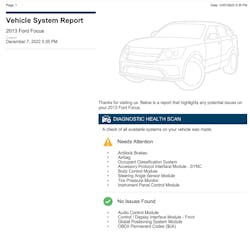
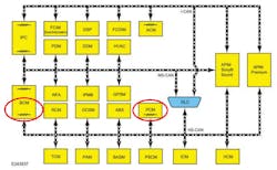
Now that my bubble had burst, I got to kick myself and regroup. I went back to my process and I reviewed my scan report (Figure 1). I noticed that the power steering control module (PSCM), the powertrain control module (PCM), and the transmission control module (TCM) are the only modules missing from the bus. At this point I reviewed the system wiring diagrams, and since I already had the TCM unplugged I started my testing there. I tested to verify the TCM had everything it needed to communicate (voltage supply, ground supply and communication signals coming in). The only issue I noted was the signal from high-speed CAN bus low (Figure 2).
The second approach
My next step was to install my AESWave LineSpi breakout box. I connected the Snap-on scope (Zeus+) to it and saw the same high-speed CAN low pattern, so then I performed a resistance check on the high-speed CAN network. This test checked the integrity of the circuit and offered me direction.
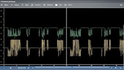
To perform this test, turn the key off (so the network isn’t active) and by connecting my Snap-on DMM across high-speed CAN+ and CAN-, you should anticipate a 60-ohm reading displayed. However, that is not the reading we were getting here, which tells us there was an incomplete circuit and one resistor was bypassed (Figure 3). I then retraced my steps to decide on which direction we go:
- The scan report showed the PCM, TCM, and PSCM are offline.
- A resistance test proved a circuit was open in the high-speed CAN network.
A review of the CAN system topology I sourced for this vehicle from Alldata showed the terminating resistors for this network are located in the body control module (BCM) and the PCM (Figure 4). But of those two, only the PCM failed to communicate.
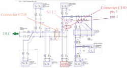
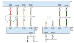
I Looked at the CAN bus network diagram (Figure 5). The communication wires pass through connector C238 to splices S109 and S110. From there, the circuit heads toward the ABS module and to connector C140. The ABS module was communicating, so I realized wiring integrity was good up to that point.
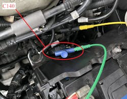
The next best place to check our signal is connector C140, which is located alongside the battery. I’ve accessed the high-speed CAN- wiring at pins 3 and 4 with my pierce probes from AESWave. (Figure 6). The circuit comes through pin 3 to splice S112, which splits the circuit (to the PSCM and back through C140 pin 4/out to the PCM and TCM).
I performed another resistance test at connector C140 (pins 2 and 3) and measured 120 ohms, but pins 4 and 5 displayed an open circuit. This confirmed the fault was between the two chosen test points.
I jumped pins 3 and 4 and communication returned, and I could talk to all modules. I then knew I would find my circuit issue between S112 and C140.
A step in the right direction
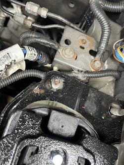
To access that section of the wiring, I removed the battery, covers and tray. Once they were removed, I saw a shiny new transmission mount looking at me. The wiring harness comes out of C140 and goes along this mount before S112. I disconnected C140 and tried to move the harness to gain access for testing, but it was pinched under the mount.
I questioned the shop owner about the new mount. Suddenly his memory came back, and he told me he had replaced the mount after he confirmed the starter was working (I'll never understand why it is so difficult to get the whole story up front).
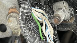
After removing the bracket, I freed the harness and removed the conduit from the harness (Figure 7). This is the extent of the damage (Figure 8). With only a slight tug on the wires individually, two of the wires instantly pulled apart. The shop let me repair the wiring, which allowed me to test the vehicle again after repairs and confirm everything was working properly at that time. I add the “at that time” reference because I know their repair caused this no-start issue, but I don’t think the starter caused the previous issue of vehicle “died while driving.” We may never know the root-cause of this vehicle’s stalling issue, but time will tell.
2021 Jeep Grand Cherokee- MIL after rear-end collision
I got a call to look at a 2021 Jeep Grand Cherokee with multiple indicators illuminated and a handful of DTCs. It was hit hard in the right-rear of the vehicle and the shop had already replaced a physically damaged module in that area. But when I got to the vehicle, it seemed all the original faults remained.
If you can't stand the heat, stay out of the kitchen
The shop owner told me he called another mobile guy first, and when he saw all the codes (63 to be exact), he turned the job down. When I asked about the replaced module, all he could tell me was it was behind the right rear interior panel. There are multiple modules in that location, but he couldn’t be any more descriptive. And of course, he threw out all the old parts. The good news is the odometer was flashing (for those of you that haven’t seen that yet, it means a module in the network needs a proxy-alignment/configuration). This is a procedure that transfers the vehicle configuration from the BCM into the new module that was installed.
I connected the factory interface (Micropod3) to the vehicle and ran the proxy procedure. The scan tool alerted me that the power liftgate module wasn’t aligned, so now I knew which module was replaced. I performed the procedure and I cleared the DTCs. I was then left with only seven remaining DTCs (four for rear parking sensors shorted to ground, two for rear radar blind spot circuits open, and one for private CAN network in the central ADAS decision module (CADM). In a situation like this one I typically choose one code and chase only that one DTC’s root-cause fault. In this case, I chose the rear radar module a circuit open (C00C4-13).
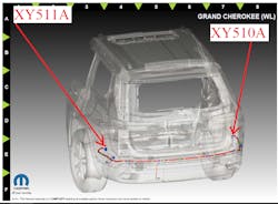
First, I asked the shop to remove the bumper so I could gain access to the wiring and modules. In factory service information, the set conditions for this DTC are as follows: “The CADM detects a power supply circuit for the left-rear mid-range radar.” A check of the OEM wiring diagram shows voltage coming in through connector XY510A pin 10 (beige/red wire) (Figure 9).
The connector is on the passenger side of the bumper and has plastic covers over both sides, making it nearly impossible to see the colors of the wires. When I removed the covers from the vehicle-side of the harness I found voltage available at pin 10 but no voltage available at the radar unit. I then removed the cover from the harness on the bumper side and I found no wire in that connector cavity. The wires that are present did not match the colors indicated in the wiring diagram.
I had another conversation with the shop owner, and they confirmed they had replaced the bumper harness. I decided to inspect the parking sensor wiring and found it’s routed through connector XY511A (which is the connector on the driver’s side of the same bumper harness) (Figure 10). I removed the covers from connector XY511A to inspect the wiring. A beige/red wire at pin 10 on the bumper side of the connector was mated to an empty cavity in vehicle side of harness. I wouldn’t have guessed this from the start, but this was a case of the bumper harness having matching connectors on both sides. This allowed it to fit (with all the connectors going across the bumper, for parking sensors) with the wire in either position. Strangely enough, there were no fitment issues and the only way you could tell there is a difference is if you looked at the terminals in the connectors. A quick swap of the harness, clearing the DTCs, and we had a functioning parking and radar system with a clean post-scan.
Both case studies were shop-inflicted issues that could happen to any of us when rushing to complete a job. Whether it is attempting to drive efficiency up or the pressure we get from impatient customers to get their car back, spending a few extra minutes on either of these jobs would have prevented these issues. They also show how following a diagnostic process and not jumping the gun saves time in the end, even if you are up against 63 DTCs!
About the Author

Chris Farley
Chris Farley is a 25+ year veteran of the industry and the owner and operator of Automedic LLC, a mobile programming and diagnostic business servicing both auto body and repair shops in central New Jersey.