Driveability and powertrain related issues
Content brought to you by Motor Age. To subscribe, click here.
What You Will Learn:
• Don't perform a test until you know what to anticipate
• Planning your diagnostic approach takes time, but will save time, overall
• Researching TSBs is something that should always be done preliminarily
Below are four case studies that were a challenge to us. But challenges help us grow stronger and more knowledgeable. We had the right tools, supportive information, and technical support on hand. But it was the great attitudes of the technicians that made it all work out in the end.
2007 Ford Mustang MIL illuminated
Our first vehicle had 90,960 on the odometer. It came in with an illuminated MIL and two DTCs:
- P0171 (System Too Lean Bank 1)
- P0174 (System Too Lean Bank 2)
We interviewed the vehicle owner to make sure what his concern was, followed by a good visual inspection. The inspection uncovered an aftermarket intake air tube and air filter. These both can be suspect when dealing with a lean mixture.
After reviewing scan data PIDs on the ATS eScanELITE we reviewed the freeze frame data. It showed:
- Bank 1 LTFT 17%
- Bank 2 16% (recorded at idle)
- MAF=5.5 gps (grams per second)
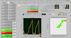
The MAF value seemed to be in the correct range for this 4.6L engine. However, knowing it’s a Ford, I thought that we had better check the MAF sensor by obtaining volumetric efficiency readings (Figure 1). That was a good call, as you can see by the test data.
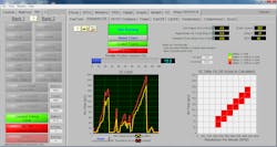
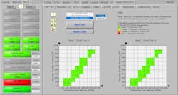
Moving on we ran the STFT and LTFT test that confirmed that the MAF numbers were a low of +22% and a high of +54% on the fuel trim chart (Figure 2). That test confirmed we had a problem with the MAF system. You may be wondering how this test can be performed if the shop you’re working in does not own an eScan. Not a problem, you must work a bit harder and use any scan tool (in generic scan mode) that will allow the user to confirm this issue. Start by checking DTCs followed by looking at freeze frame PIDs. Viewing the high fuel trim reading on a generic scan tool (other than eScan), most of the time will not provide you with a defined failure of the MAF.
The eScan makes our job easier when working on driveability and/or check engine light problems. The test for fuel trim on eScan allows us to view the fuel trim numbers. The high values exhibited, (from the bottom to the top of the chart) is always a good indication that the MAF can be the issue.
The next step on a generic scan tool would be to graph the Calculated Load PID and to make sure that the test reading can obtain 90% load (at sea level but adjust for elevation) as you press the pedal to the metal. Always make sure that the road in front of you is clear and safe (nothing worse than crashing into something. After all, we want you to stay in one piece). A one-car length is all you need to complete the test and view results along with another length to repeat the test. The eScan makes testing a breeze but if you do not have one you have to work with the tool you have. Remember, you can run the tests on any scan tool in generic mode by using the steps I outlined above.
The problem on the Mustang was not the usual MAF sensor issue, but rather something that was a related item. We tried cleaning the MAF sensor (as a first step) but did not see any improvement, so we RTFI (read the fricking information) and found that some aftermarket intake air tubes can cause an issue, mimicking a MAF sensor problem. We called the dealer to order a new OE intake tube and were told that it was no longer in production or available.
The next step was a Google search, which came up short, so we called LKQ (a salvage yard), found a used OE intake duct, and installed it. The engine was now running the way it should, with the MAF values back to normal. The only procedure we had left to complete was to reset the adaptive fuel trim before shipping the vehicle.
2013 Audi A4, repeated MIL after dealer-service
The next vehicle was one of our new customers. He arrived with his 74,111-mile vehicle. He told us that he had regularly serviced the vehicle (at the Audi dealer) from when it was new. The Audi owner proceeded to tell us that he was no longer happy with the dealer service. Since his recent vehicle service, the check engine light was now illuminated.
After more than a couple of trips back to the dealer (along with more money spent) the check engine light came back on. The dealer replaced the spark plugs and ignition coils (along with some other service items) before returning the vehicle to the owner. The MIL returned shortly after those repairs and the Audi owner returned to the dealer. He was advised to leave the vehicle once again.
The fed-up owner decided to search for a different repair facility to diagnose and service his vehicle. The dealer’s mistake cost them a good customer that turned out to be a win for us. When we received the vehicle, we explained to the vehicle owner that we would have to perform a diagnosis before we would recommend any service or repair anything.
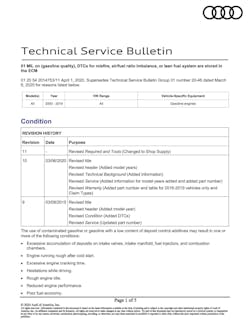
After a good visual inspection, we followed up with a search for TSBs. It yielded two important bulletins. One bulletin was on gasoline quality and carbon build-up (which is very common) (Figure 3). I have written about carbon build-up issues on Audis and VWs in other Motor Age articles where we came across misfire problems on cold engines.
On our problem vehicle, we waited for the engine to cool down before we installed a video scope into the engine. We examined the condition of the valves and pistons. The valves and cylinders did not look carboned-up enough to cause the misfire problems that this engine produced.
We reviewed the information from the scan data on the following DTCs:
- P0301 - (Cylinder 1 Misfire)
- P0302 - (Cylinder 2 Misfire)
- P0303 - (Cylinder 3 Misfire)
- P0304 - (Cylinder 4 Misfire)
- P0171 - (System too Lean)
Knowing the DTCs assisted us to develop a plan on repairing this Audi. We understood that a misfire can be caused by many things (such as spark, fuel, engine-mechanical, carbon build-up, a cracked flex plate, crank sensor, and a few other things). We just needed to narrow it down to the correct problem.
Franklin (the technician) ruled out the previously mentioned and looked at the second bulletin. It stated misfires P0300, P0301 to P0304 can be associated with ignition coil issues. Since the coils were already replaced with OEM coils (along with the spark plugs), we had to move on.
The next thing we found is something we always check for, crankcase pressure. In ALLDATA they had a community article that referenced a P0171 problem. It was associated with crankcase pressure issues (aka, the breather / PCV system). We used our manometer to check the crankcase pressure and found it was out of specifications.
With the manometer connected, we viewed a crankcase pressure reading of 125 mbar (way over the specification of 97mbar). Franklin connected the Smoke Wizard smoke machine and notice the flow meter ball was way up the top of the flow scale, indicating a large leak somewhere.
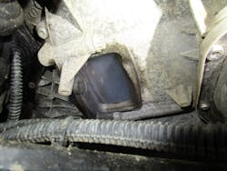
There was no smoke visible from the top view of the engine, so we lifted the vehicle and found the smoke coming out of the engine/transmission inspection cover (Figure 4). The excessive crankcase pressure was caused by a clogged breather / PCV system, and resulted in a blown-out rear main seal. We explained to the Audi owner that we had to drop the transmission and then remove/installed the rear main oil seal. The job would also entail changing the breather / PCV components to fix the root-cause of the fault, and make sure the engine was able to breathe properly.
We received the OK from the vehicle owner, along with getting approval for replacement of the rear brakes, starter, shifter cable, flywheel bolts (that were a one-time use), and a driver’s side mirror. We installed all the needed parts. We retested the breather/PCV system using the manometer to make sure the engine was operating as designed.
After clearing the DTCs and test driving the vehicle we confirmed all the Monitors were “Ready,” along with no suspect Mode 6 data, pending DTCs. We now acquired a good customer since we repaired the root cause of his concern of the rough running engine. We built the vehicle owner's confidence level through good communication, including showing him scan tool screenshots and pictures of the problem before making any repairs. We followed that up with the after-repair scan tool screenshots when the vehicle was completed. Using digital inspection can be a very important tool for your shop.
2011 Nissan Pathfinder, MIL illuminated
Our third problem vehicle had 177,225 miles and came in with a P0101 (Mass Air Flow Sensor Range/Performance), along with an illuminated MIL and performance issue. We connected our eScan to diagnose the vehicle and check the freeze frame data carefully.
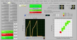
The data stream for this 4.0L indicated the MAF sensor was only reporting 3.59 grams per second of airflow, at idle. We followed that up by running the volumetric efficiency test to see where the MAF reading was, under loaded conditions. Test results confirmed the MAF is not reporting properly (Figure 5).
The next step was to use CRC MAF cleaner to see if there was an improvement. Because there was no difference after cleaning, my technician, Bill, took into consideration the mileage of the vehicle and ordered a new Hitachi MAF sensor then installed it. After the new MAF was installed, the codes cleared, and the vehicle was taken on a test drive. That resulted in 3 emissions monitors not being able to run to competition.
Bill looked up the monitor run criteria and then took it for another couple of test drives. The monitors still would not run to completion. Bill moved on to research information in Alldata, ProDemand, Identifix and found TSB NTB12-051k (regarding PCM reprogramming for MAF code).
Now, it was time to contact the vehicle owner and explain the issue. The vehicle owner was OK with the repair and agreed to proceed with the programming. Since Bill was tight on time, he decided to use the OPUS RAP2 box to reprogram the vehicle. The RAP2 is a great tool to have around, especially on a Nissan (they can be a bit of a pain to program, and tend to take a long time, in most cases).
An OPUS Nissan tech instructed Bill to connect a battery maintainer and follow some minor instructions before they took over remotely to program the PCM. After hours of programming, another test drive was performed that was not successful. Bill’s next step was to perform a hard reset. This is done by turning the ignition key off, followed by removing the battery cable ends from the battery post. Then, connecting a 1 ohm - 10-watt resistor (in series) to bring down all the capacitors in the computers.
This was followed up by cleaning the throttle plate, and a test drive that resulted in an illuminated MIL, but 4 out of the 5 monitors “Ready.” Bill was beside himself (since the MIL was off before programming and no DTC were present prior), so he called OPUS tech support. The OPUS tech recommended not using any other brand MAF sensor other than the OE dealer part. Bill told the tech support agent the MAF was an OE Hitachi, the same brand as the one installed currently on the engine (that we purchased from WorldPAC). The tech had Bill check the part number off the old sensor and compare it to the one that was in the vehicle; they were not an exact match.
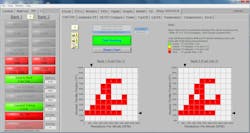
We followed the OPUS tech’s recommendation and took a ride to the dealer to purchase the Nissan Hitachi MAF. It had a few different numbers than the OE Nissan one we purchased. After the new dealer-MAF was installed, all the monitors were now “Ready” and there was no MIL illuminated. The fuel trim and volumetric efficiency tests both passed will flying colors (Figure 6+7). Sometimes strange things occur on certain vehicles (as in this case) when only the OE dealer part will work. The help from OPUS saved the day on this Pathfinder.
2012 Chrysler Town and Country, overheating warning/MIL
The last vehicle in this article that came in had 62,990 miles on it and a complaint of the temperature gauge reading high/check engine light on. After connecting the ZEUS scan tool, we were able to view more than just one DTC on the vehicle scan report. The DTCs that were reported were:
- P0480 (Cooling Fan 1 Control Circuit/Open)
- C212A-16 (Antilock Brakes System voltage below threshold)
- P0692 (Cooling Fan 1 Control Circuit High)
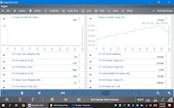
Bill looked up service information in MotoLogic to review how the circuit works, and what color wires went from the PCM to the component. With the scan tool connected we looked at the data to see if the fan was being commanded on (Figure 8). As you can see the cooling fan was not receiving the correct command. Both the engine and transmission were at the recommended temperature for the fans to operate.
I always suggest in my classes to go to the load in the circuit and see if it works (so you can rule out the load as the issue). With the wires disconnected from the fans, we connected the Power Probe Hook, and applied voltage/ground to see if the fans would come on; they did. So, that ruled out the loads as being the issue.
We checked and found all necessary voltage supplies, grounds, and continuity in the load circuit were OK. We hooked up the eScope to all the terminals of the low cooling fan relay and warmed the engine up.
The test indicated that there was no signal received (from the command relay) to turn the fans on. This left us with the only logical conclusion that the TIPM circuit board was bad. We ordered a Dorman / NAPA TIPM and installed it. We cleared the DTCs then warmed the engine up from a cold start to make sure the fans worked as designed. With the vehicle repaired we called the customer and sent the cool vehicle on its way.
Efficient and accurate diagnostics comes from a combination of factors. Having the correct tools and knowing how to implement them, in combination with the correct service information will get you very far, but certainly not without an understanding of how the systems are designed to work and what to anticipate.