Advanced diagnostics: Approaching a diesel engine mechanical fault

Content brought to you by PTEN. To subscribe, click here.
Not a heavy-duty diesel tech? That’s fine; neither am I. But one tried-and-true method of acquiring new knowledge is to implement the tools we’ve learned to trust and invest some time in some research. This combination has served me well in developing hypotheses and proving them out through experimentation.
The task at hand
The subject of the day, a huge Caterpillar 14.7L 3406e diesel engine situated in a Kenworth W900 dump truck (Figure 1). The truck comes to us with the complaint from the operator that the powerplant's compression brake doesn't seem to slow the vehicle as it has in the past. With a little research and input from my brilliant HD tech friend and instructor, Brent Delfel of Advanced Diagnostic Consulting, I’d like to show you what I have learned from him.
The compression-brake system assists in slowing the tremendous vehicle in two ways. First, utilizes the compression stroke of the large diesel engine to slow the crankshaft down. At the top of the compression stroke, the highly pressurized cylinder charge is then “wasted”. Just at the point when combustion of the diesel fuel would normally occur, the delivery of the fuel is canceled and the exhaust valve is momentarily allowed to open. As a result, compression is shed on the exhaust stream.
A moment later, the exhaust valves are allowed to close, sealing the cylinder once again. The piston will continue to descend on what would normally be a power stroke. Instead, as it is descending a negative pressure (or “vacuum”) is created in the cylinder, on top of the piston. This vacuum in the combustion chamber is what also assists in slowing the crankshaft down. Engine-braking occurs when there is no accelerator input and the clutch engages the engine and the transmission. As long as the engine is mechanically connected to the transmission and road wheels, the vehicle will slow as well. This is why it's called an "engine brake."
There are three levels of engine braking (low/medium/high). In low, only two cylinders have engine-braking capability (cylinders 3 and 4). Medium allows for four of the cylinders to provide engine-braking capability (cylinders 1, 2, 5, and 6). High allows for all six cylinders to provide engine braking.
How is the goal accomplished?
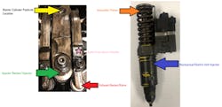
Now that I have an understanding of the system’s goal, I can begin to understand how that goal is carried out. The first thing we have to understand is that this Caterpillar uses mechanical electronic unit injectors (MEUI). The engine’s camshaft has an additional lobe (for each cylinder) to operate an intensifier piston on top of the injector itself (Figure 2). The ECM will command the Injector solenoid on/closed to trap the fuel in the injector. The cam lobe will operate the rocker/piston and with the injector solenoid energized the trapped fuel will be pressurized and delivered to the combustion chamber. When the solenoid is off, fuel is not trapped but vented from the injector to a return fuel circuit.
It’s this same rocker that is used to operate the injector piston that is also used to operate the engine brake system. As the rocker is driven by the camshaft, it pivots on a fulcrum, like any other rocker. The cam shaft-side lifts and the injector-side travels down (like a seesaw). It’s the upward motion of the rocker that drives a pushrod connected to a master hydraulic cylinder (Figure 3). This system diagram is drawn in a state of “engine-brake operation” and demonstrates only one cylinder’s circuit but functionality is the same for all six cylinders.
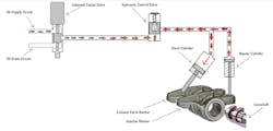
System operation
Pressurized oil is supplied from the engine. During normal operation of the engine, the oil is vented back through the oil drain circuit via the de-energized solenoid control valve. However, when engine-braking is called upon, the solenoid control valve is energized by an ECM and allows supplied oil to reach the hydraulic control valve which is being held closed by a spring.
As the pressure of the supply oil overcomes the spring tension of the hydraulic control valve, the valve begins to shuttle and unseats the check-ball as well. Supply oil is then allowed to fill/feed the hydraulic circuits of the master and slave cylinders. This will cause the master cylinder pushrod to extend and come into contact with the Injector rocker at the camshaft (as indicated by the yellow arrow in Figure 2).
The motion of the cam lobe operates the injector rocker and drives the pushrod of the master cylinder up. As a result, the oil in the feed circuits is displaced, and the check-ball in the hydraulic control valve seats. Pressure begins to increase in the hydraulic circuits as the oil is now trapped and the master cylinder pushrod is displaced by the rocker.
The movement of the master cylinder pushrod is transferred in the hydraulic circuit, to the slave cylinder and it extends to operates the exhaust valve rocker (this area can be seen on Figure 2 and is indicated by the pink-colored star). Compression is vented to the exhaust stream and the valve will close as the lobe of the injector rocker rotates past its apex.
When the ECM de-energizes the solenoid control valve, the supply oil is vented. Spring tension forces the hydraulic control valve to shuttle closed and the high-pressure oil in the master/slave cylinder circuits is vented to the top of the hydraulic control valve. Normal engine operation is restored.
Watching the system in action
So, how can we use tools to monitor this system? A better question may be "Why would we want to?" Seeing a system in operation will allow us to determine what "normal" looks like. And, as I always say…
”If we know what ‘Normal’ looks like, ‘Bad’ sticks out like a sore thumb.”
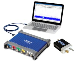
Using a capable lab scope and pressure transducer [in this case, a PicoScope and WPS500 (Figure 4)], we can not only see the changes in pressure of the exhaust system but we can also correlate these changes to specific cylinders. In plain English, it can help us determine why the “engine-brake” system may not be functioning as it should and which cylinder(s) are at fault.
With what was described above, we are now aware that the compression pressure harnessed in the cylinder is then vented to the exhaust stream. This event occurs just before the top of the compression stroke. Meaning, a pressure spike should be visible at this time, in the exhaust stream. All pressure spikes should be visible from each engine-braking cylinder and they should all be similar in amplitude (pressure-value).
Look at the capture (Figure 5). The channels are as follows:
-BLUE= CKP sensor signal
-GREEN=Exhaust system pressure pulses
This capture was taken during a deceleration event, in “high” mode (all cylinders were commanded to provide engine braking). Referencing service information, the firing order for this engine was determined to be 1-5-3-6-2-4. In a known-good capture, it was determined that the #1 fuel injector (fired near TDC of the compression stroke) was occurring at four CKP pulses to the left of the CKP sync pulse. On the screen is two full engine rotations (one complete engine cycle) representing 720 degrees of crankshaft rotation.
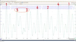
The waveform was partitioned equally in six ways to associate the pulses with each of the six cylinders. As can be seen, two of the six pulses are considerably low compared to the other four. This lack of engine-braking contribution can likely be attributed to low cylinder compression.
A relative compression test was performed and it was determined that multiple cylinders had a loss of integrity but cylinders 5 and 3 were the worst offenders. The point is not that the vehicle requires repair. It’s not even the fact that we can see the variances in the exhaust pressure waveform. The true point is that we can take what we know from our past experiences and the results of the tests we have grown to trust, and apply them to what we are trying to now understand. I think we've proven that as a success in this case.
The shop was instructed to carry out the next step of a cylinder pressure leakage test in cylinders 5 and 3. I don't have a conclusion for you at this point as the truck is awaiting further testing but again, that wasn't the point of this article.
Being familiar with the tools we choose to implement, taking the time to educate ourselves on the systems we face and the components of that system, we can capitalize and learn testing techniques that you will likely never see published in service information.
The best part is these same tools and techniques will likely yield you the information you desire with far less time and energy invested than that which is published in service information and so heavily relied upon throughout the rest of the industry. Be different, take a new approach and learn how to learn. It will serve you well for the rest of your days, I can promise you that!
About the Author

Brandon Steckler
Technical Editor | Motor Age
Brandon began his career in Northampton County Community College in Bethlehem, Pennsylvania, where he was a student of GM’s Automotive Service Educational program. In 2001, he graduated top of his class and earned the GM Leadership award for his efforts. He later began working as a technician at a Saturn dealership in Reading, Pennsylvania, where he quickly attained Master Technician status. He later transitioned to working with Hondas, where he aggressively worked to attain another Master Technician status.
Always having a passion for a full understanding of system/component functionality, he rapidly earned a reputation for deciphering strange failures at an efficient pace and became known as an information specialist among the staff and peers at the dealership. In search of new challenges, he transitioned away from the dealership and to the independent world, where he specialized in diagnostics and driveability.
Today, he is an instructor with both Carquest Technical Institute and Worldpac Training Institute. Along with beta testing for Automotive Test Solutions, he develops curriculum/submits case studies for educational purposes. Through Steckler Automotive Technical Services, LLC., Brandon also provides telephone and live technical support, as well as private training, for technicians all across the world.
Brandon holds ASE certifications A1-A9 as well as C1 (Service Consultant). He is certified as an Advanced Level Specialist in L1 (Advanced Engine Performance), L2 (Advanced Diesel Engine Performance), L3 (Hybrid/EV Specialist), L4 (ADAS) and xEV-Level 2 (Technician electrical safety).
He contributes weekly to Facebook automotive chat groups, has authored several books and classes, and truly enjoys traveling across the globe to help other technicians attain a level of understanding that will serve them well throughout their careers.