Content brought to you by Motor Age. To subscribe, click here.
CASE STUDY:
- 2016 Chevrolet Cruze
- Mileage: 149,694
- 1.4L Turbocharged
- Automatic Transmission
- No Crank
We all have responsibilities, and for most of us, that includes waking up early enough to get to work on time. Maybe you can transition from dream state to consciousness without assistance, but those of us who don’t know how to regulate our late-night television-streaming addiction requires an act of God and a giant cup of coffee to get going in the a.m.
What happens when that act of God doesn't occur? We may not wake up on time, we’ll probably catch up on some much-needed sleep (my favorite part), and our work is delayed or not carried out at all. What does any of this have to do with automotive diagnostics? Well, you’ll see, as I’ve been excited to share this story with you!
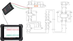
The legend begins with a local shop owner calling to ask if I could help with a Chevy Cruze he was struggling with. The vehicle was towed to him with a no-crank concern and the key wouldn’t come out of the ignition (FIG 1). The vehicle would power up, but a no-crank concern was present, and the key was in fact, stuck in the ignition.
We performed an auto scan which allowed us to request fault information from all the vehicles' supported modules. The result showed seven fault codes that we retrieved from the 10 modules that responded to our auto scan:
-The ECM (Engine Control Module) had two fault codes; U0121:00 - Lost communications with the EBCM (Electronic Brake Control Module) and U0140:00 – Lost Communications with BCM (Body Control Module).
-The TCM (Transmission Control Module), Inflatable Restraint Sensing and Diagnostic Module, HVAC Control Module, and Passenger Presence Module all had a U0140:00 – Lost Communications with the BCM fault code and the Radio had a U0020:00 Low Speed CAN Bus fault code.
-The Chassis Control Module, Instrument Cluster, Multimedia Player Interface Module, and Telematics Communication Interface Control Module reported back with no fault codes.
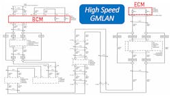
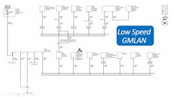
Fourteen modules came back with a No Response status. We suspect that the vehicle was not equipped with most of these modules, but our experience and the fault codes retrieved tell us that it had to be equipped with an EBCM, PSCM (Power Steering Control Module), and a BCM. When we looked in our service information system for Data Communication Schematics, we found what we were looking for (FIG 2 & 3).
Building a game plan
When modules are unresponsive, I like to analyze the network diagram. During this process, if I consider which modules are and are not responding, I usually get a pretty good idea whether we are dealing with a network issue and if that is the case, the type and location of the fault start to become clear. Starting with the BCM, let’s focus on the unresponsive modules that the vehicle was equipped with.
The BCM is a Gateway module. It serves as an interpreter for module-to-module communication between modules on one architecture to modules on another architecture. We know that modules from both the High-Speed GMLAN and Low-Speed GMLAN are reporting a loss of communication with the BCM.
We’re not ready to rule anything out but it is unlikely that we have circuit faults on both of those networks. If you look at the High Speed GMLAN diagram you’ll see that this network is configured like a daisy chain, with the BCM at the start of the network and the ECM at the end of the network (FIG 2).
With this configuration, if there was an open circuit anywhere in the network, scan tool to module communication would not take place with any module that is downstream of the open circuit. Module-to-module communication also wouldn't take place from one side of the open to the other. When we consider this, there's no way that we're dealing with an open circuit in the High-Speed GMLAN network. “We can’t talk to the BCM, but we can talk to the Telematics Communication Interface Module, Chassis Control Module & the ECM.
Keep in mind that the Telematics Communication Interface Module is also on the Low-Speed GMLAN, so the scan tool may be talking with this module over that network (FIG 3). We would need to do some digging to determine this for sure, but doing so is not necessary. The fact that we can communicate with the Chassis Control Module and the ECM makes this point irrelevant. If we consider other possible circuit issues, we’d be left with a short to B+, short to ground (B-) and the two CAN circuits shorting together. If any of these faults were to occur, it would likely affect communications with all the modules on this network.
There are still a lot of unanswered questions. When attempting to solve these riddles, it’s a good idea to consider all the puzzle pieces, but after a while, I find that focusing on the things that I don’t know can be overwhelming. Clarity comes to me when I concentrate on what I do know.
At this point, we know that several modules are reporting that the BCM is not talking, we have no scan tool to BCM communications, and it doesn’t appear to be due to a network circuit fault. Like me, you’re probably suspicious of the BCM but that may or may not explain some of the other symptoms that we’re experiencing. Regardless, even if we wanted to condemn the BCM, we couldn’t do so without checking the BCM battery voltage, ignition voltage, and ground circuits at the BCM. This was our next task and finding the location of the BCM, printing out a wiring and connector terminal diagram was the first step in this process.
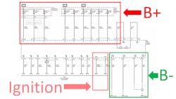
We’ve located the BCM, and we know where the battery positive, ignition, and ground circuits are. We’ve also identified the connectors so, now we can get to work. According to the appropriate wiring diagram, there are nine battery positive circuits (FIG4). We used a test light (connected to battery ground) and we left the connectors plugged-in with the key in the “ON” position. We touched the battery positive terminals with the probe and the test light illuminated on all nine of these circuits.
Please be aware, load testing circuits appropriately is important. Some may feel like a test light might not be an appropriate load but considering that we’re dealing with an unresponsive module, we felt like a test light was plenty electrical load for testing these circuits. If we were testing a circuit that was intended for higher current, then we’d use a load that closer matched that of the circuit.
Next, we needed to check the ground circuits. According to the diagram, there are four ground terminals that needed to be tested. We moved our test light clip to the battery positive post and touched the probe of the test light to these four ground circuits, with the BCM connectors plugged-in, and the key in the “ON” position. When we did, the test light illuminated for all four ground terminals at the BCM.
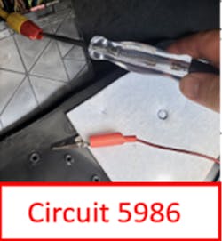
Finally, we need to check the ignition circuits and according to the diagram, there are two. We moved the clip of the test light back to the battery negative post and touched the probe of the test light to the two ignitions circuits, with the connectors plugged in and the key in the “ON” position. When we did, the test light illuminated when touching terminal 22 of connector X4 (which is circuit 5985) but it did not illuminate when touching terminal 23 of connector X4 (which is circuit 5986) (FIG 5).
Target Acquired
Well, this is interesting! Both circuits are labeled “IGN” on the diagram (FIG 4) but only circuit 5985 lights the test light when the key is on (circuit 5986 does not). We need to see where this circuit comes from.
On this diagram, it’s not clear if this is an “Ignition Voltage feed” for the BCM or a “BCM output.” Maybe there’s more information about this circuit in other diagrams. This is getting exciting but before we start researching that circuit, let’s check the High-Speed GMLAN circuit activity at the BCM when attempting to communicate. Said another way, let’s scope it!
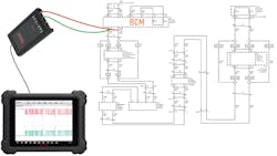
As I mentioned earlier, having a network fault is not likely, but we didn’t rule it out completely. So, as some of my industry-friends say, “let’s scope all the things.” Now, most of you probably noticed something that I just said, and I think it's important to call it out. I said that I wanted to scope the High-Speed GMLAN when attempting to communicate with the BCM. I say that because even though this fault has never given us the impression that it's intermittent, I think it's important to always verify that the fault is present during the test that you're performing. If we perform a test without verifying the fault is present during the test, then the results of the test are inconclusive. We're going to have a scan tool on the vehicle and verify that the BCM is non-responsive. This will be carried out while connecting our scope test leads to the High-Speed GMLAN. The test will be conducted twice. First, the leads will be placed at the BCM's connector X1, terminals 24 and 25. Then, connector X2, terminals 23 and 24. Only one test is displayed here (FIG 6).
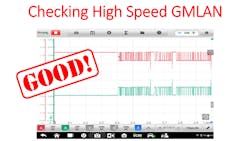
As most of you know, this is a high-speed CAN network, so there should be 2.5 volts on both circuits when at rest (“recessive”) and the CAN+ should toggle from 2.5 volts to about 3.5 volts during communication packets (“dominant”), and the CAN- should mirror CAN+ by toggling from 2.5 volts to about 1.5 volts during communication packets.
We set our time-base to 100 microseconds per division. Channels A & B were set to the x1 probe with a voltage setting of ±5 volts and we recorded the capture. When we did, the results agreed with our suspicions. The High-Speed GMLAN bus is not the cause of our lack of communication with the BCM (FIG 7).
If this was a murder case, Jessica Fletcher and Columbo would be all over the BCM but don’t forget, they have that other pesky suspect to consider. That’s right, we’re talking about that slippery, no-good circuit 5986. What do you say we do them proud and start putting a little pressure on that circuit?
Honing in on the root-cause
We need to understand this circuit. On the diagram (FIG 4), it’s simply labeled “IGN.” It would be easy to assume that we’re missing an ignition switched voltage supply to the BCM but that may be a dangerous assumption.
After researching, we determined that the Body Control Module is the Power Mode Master. There’s a lot to this designation but the part that’s most relevant to this scenario is the fact that the BCM is responsible for waking up certain modules. That would make the BCM the alarm clock for those modules.
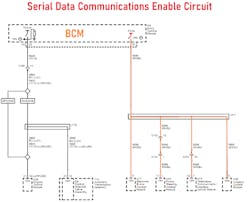
If the BCM’s alarm clock isn’t working, then the modules it’s responsible for waking up, will not be communicating. In other words, they will either be late or not show up to work at all. Can you guess what circuit the BCM uses to enable module communications? That’s right, circuit 5986, and it’s called “Serial Data Communication Enable” (FIG 8).
It turns out that the BCM should provide system voltage to this circuit when the key is on. This is the wake-up signal that these modules need to come to life and start communicating. This is the "Act of God and a giant cup of coffee” that we spoke about earlier.
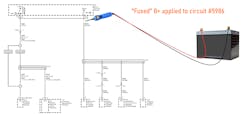
We can assume that replacing, programming, and setting up the BCM will resolve our concerns, but I can think of one test that we can perform that would make us feel a little more thorough and comfortable about moving forward with the replacement of the BCM. We can prove the BCM replacement will indeed fix the issue. We decided to apply voltage to the circuit and see what modules respond to our auto scan (FIG 9).
When we did, every module that the vehicle was equipped with was communicating except the BCM. That included the EBCM, PSCM, and the Steering Wheel Angle Sensor Module (which were unresponsive earlier). It’s probably no surprise that there were still a lot of U0140:00 – Lost communications with the BCM codes.
I think it’s safe to say that we have our perpetrator. I feel confident that if we replace, program, and set up the BCM, our no-crank and communication concerns will be resolved but there’s something that I’m not comfortable with.
When you look at the Enable Serial Data diagram (Figure 8), you’ll see that the BCM uses circuit 5986 to enable serial data communications with the Electronic Brake Control Module, Power Steering Control Module, Telematics Communication Interface Control Module, and the Chassis Control Module. Why are we always able to communicate with the Telematics Communication Interface Control Module and the Chassis Control Module?
If you recall, the Telematics Communication Interface Module also communicates over the Low-Speed GMLAN (Figure 3). It may use Low-Speed GMLAN for scan tool communication but that doesn't explain the Chassis Control Module. Why the heck was the Chassis Control Module awake and talking?
If you look at the Serial Data Power Mode Master description, you’ll see that it says that modules that have switched voltage inputs may operate in a default mode if the wake-up circuit doesn’t match their switched voltage input (FIG10). To quote Scully from The X-Files, “Nothing happens in contradiction to nature, only in contradiction to what we know of it.”
After we replaced, programmed and set up a replacement BCM, we performed another auto scan and all equipped modules responded. Bonus! The engine started and the key would now come out of the ignition lock cylinder! Yay!
Well, there you have it! The next time you’re frustrated with a vehicle that you’re working on, don’t call it names like you normally do. Be nice. You probably have more in common than you think. You both probably rely on a wake-up call to get to work on time.
I’ll leave you with a thought. What things do you think would’ve been condemned if I or someone else didn’t take the time to thoroughly see this one through?
About the Author

Brin Kline
Owner of Assured Auto Works
Brin Kline is the owner of Assured Auto Works in Melbourne, Florida, an automotive general repair business with a mobile diagnostic and module programming division. He has been in the automotive industry for 27 years. Kline also teaches for Carquest Technical Institute and Trained by Techs, is a member of the Automotive Service Association’s Mechanical Operations Committee, and president of the Automotive Service Association (ASA) of Florida.
Kline also reviews a variety of tools for Professional Tool & Equipment News. To read his tool reviews, search his name on VehicleServicePros.com.
