Content brought to you by Motor Age. To subscribe, click here.
What You Will Learn:
• DIN is a standard in Europe, much like our SAE in the United States
• Standards mean we should familiarize with DIN because it applies to everything
• With practice, DIN can be as easy to analyze the diagrams we are accustomed to
It’s only natural for technicians to stick with what they know (especially diagnosticians). It's because of how we were raised in this industry. We've learned a thing or two from our mentors, other technicians in the shop, and instructors in a classroom atmosphere. Often, because what they've learned works for them, it likely works for us (or we wouldn't be using it, right?).
Well, when it comes to electrical concerns (specifically, analyzing wiring diagrams), most of us steer clear of the DIN or "Euro" wiring diagrams. The reason being is it's just different. And, many times "different" is uncomfortable. But, it doesn't mean we can’t learn to capitalize on what DIN wiring diagrams have to offer.
DIN (Deutsches Institut für Normung e.V.) is an organization in Europe much like our Society of Automotive Engineers (SAE) that is responsible for many of the standards established in Europe. The DIN wiring diagram (also referred to as the track diagram) is one of them. Rumor has it that it came about because (at the time) a large number of people in Europe were afflicted with color-blindness (making wiring diagram analysis tough). I can't be sure from where that information came, or if it is even partially true. But I can tell you that one doesn’t need perfect vision to utilize the DIN wiring diagram.
The electrical roadmap
I first want to note that the goal of the analysis is the same, regardless of the path taken. We gather information to educate ourselves about the system or components we are addressing. Sometimes that information is about how a system functions to carry out a goal (that information can be found in an adequate service information source).
We can reference block diagrams that offer a basic overview of the system layout. We can also read about how systems strategize, how their functionality is monitored, and even what thresholds must be crossed to distinguish proper functionality from failure.
At other times, we are more interested in discovering why a system cannot carry out that goal and (more specifically) where the breakdown in that system is located. This is when it’s often necessary to reference a wiring diagram. The wiring diagram most of us are accustomed to (SAE standards) offers us lots of information about the circuit and components that make up that circuit.
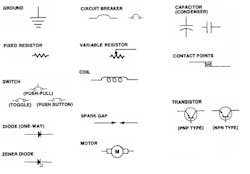
The entire circuit(s) is/are laid out over a single page or a series of pages, far smaller than the actual circuit on the vehicle. Learning what the symbols and numerical codes on the diagram represent allows us to identify many aspects of the circuit. For instance, the symbols represent components in a circuit can be seen here. (Figure 1). Just a few other aspects are listed below:
- Wire color/size
- Connector terminal number
- Pin identification (male or female)
- Component symbols
- Call-outs within the components
The above are just a few of what the SAE wiring diagram has to offer. The diagram serves as a roadmap to help guide the technician through an electrical diagnosis, and with practice and an understanding of electrical fundamentals, a technician can make light work of even the most complicated circuits. Considering the hundreds of feet of copper wire and complicated, multiplexed circuitry strung throughout the vehicle, I recommend taking every possibility I could scavenge when it comes to gaining an edge on the diagnostic approach. Mastering wiring diagram circuit analysis is likely the most valuable skill one could possess in the automotive diagnostic and repair industry. It allows us to gain a sense of direction before approaching the vehicle, which saves loads of time.
What makes DIN different?
Naturally, the following question to ask is "why spend the time familiarizing yourself with DIN wiring diagrams, if an SAE wiring diagram is available?” It depends on personal preference. But sometimes, a wiring diagram you may desire is not available in SAE format (like some of the European cars). What then? I mean no offense at this but to think that some would simply pass off the job because they weren't comfortable with the DIN wiring diagram, I feel is a bit of premature abandonment, to say the least. But, I’m sure it’s simply due to fear of the unknown.
Truth be told, the DIN wiring diagram is not all that different or difficult to use. It just takes some time to understand what the diagram is trying to tell you (sound familiar? You had to overcome the same challenges with the SAE wiring diagram at some point in your career).
What makes DIN wiring diagrams great is that they are created from the standards described above. One of those standards defines wire terminal designation. This identifies the type of circuit. This is tremendously beneficial to us, because regardless of the European car we are addressing, the terminal designations must be the same; it’s the law! (Figure 2)
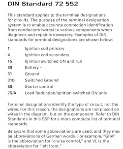
For instance, battery source voltage can always be found at a terminal labeled "30." The same can be said about terminal "31;" there should always be battery ground available at that terminal. Terminal "15" will represent switched ignition voltage, meaning the source voltage will be found at that terminal whenever the ignition switch is turned to the on/run position. A terminal labeled “50” will have source voltage available at it with the key in the “crank” position (what you should find at the starter motor S-terminal during cranking conditions). A terminal labeled “X” is one described as load reduction, meaning it’s only supplying voltage when the engine is running/cranking or at initial key-up (like a fuel pump supply relay).
Ever wonder why the four or five-pin relays we see from day to day are labeled as “85, 86, 87, 87a, 30?” Well, you can thank DIN for that, too. "85" and "86" represent the coil side of the relay. "85" was typically the ground side of the coil and "86" was the voltage source side of the coil (however, they've proven to be reversed at times). Now, as for the switched-side of the relay, Terminal "30" is (yep, you guessed it) "voltage supply" and terminal "87" was the output of the relay, to the circuit being supplied by the relay.
Understanding the DIN diagram Is key
What many fail to realize at first is that the DIN wiring diagram is created using symbols as representations of components (such as load devices, switching devices, etc.), just like the SAE diagrams. These symbols used to define components are also standardized, meaning they conform to DIN specifications (Figure 3). Alphanumeric characters are also used to describe what each component is. In other words, both a power window regulator and engine starter are DC motors. Both of which would be represented by the same symbol; however, the alphanumerical code next to the symbol differs between the two of them.
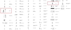
Why is this important to know? Well, the SAE diagram accomplishes the same goal but goes about it a bit differently. The SAE wiring diagram will call out the component by name, right on the diagram itself. However, the DIN wiring diagram requires the tech to decipher the alphanumeric code. It simply takes up less space on the diagram and organizes is a bit more (in my opinion). These representations or codes can be found in the diagram key. By identifying the component on the diagram, the technician would simply note the alphanumeric ID associated with the component. One would then reference the key to properly identify the component. This could also be performed in reverse order. By first locating the component of interest on the key, one could then locate the symbol representing the component on the diagram. I’ll demonstrate shortly.
Taking DIN for a test drive
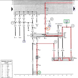
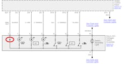
The same information found in SAE diagrams is deciphered on the DIN wiring diagram as well. However, one of my favorite aspects of the DIN wiring diagram isn't always found in the SAE wiring diagram, and that is how the DIN wiring diagram pays regard to current flow. DIN wiring diagrams are often referred to as current-flow diagrams. The reason for this is quite simple. Electrical current flow is typically depicted on the DIN wiring diagram as flowing from the top of the page, towards the bottom. This greatly simplifies circuit analysis. Don’t take my word for it; let me show you (Figure 4). For demonstration, I’ve chosen a blower motor circuit from a 1999 Volkswagen Jetta.

Beginning at the top of the page, there are a series of lines running horizontally through the fuse box. We can see that the splice point (represented by the black dot) is connected to line “X”. We know this terminal is only energized when the ignition is in the “on/run” position. We learned that earlier.
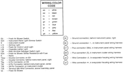
Refer to a legend of that circuit’s components and wiring connections (Figure 5).
Current will then flow through the 30A Fuse #6 (VW Identifies their fuses as “S”) and travel down a Black wire/red tracer, through an 8-way connector, at terminal #1 (which I’ve encircled in ORANGE). With the Fresh Air Blower Switch (“E9”) in its drawn position, electrical current will travel through a white wire and then across all three resistors of (“N24”) the blower resistor block. It will exit the resistor block on a red/black wire and pass through another 2-way connector at terminal #1 before the dropped voltage is available to the blower motor ("V2"). The circuit finds chassis ground by leaving the same 2-way connector (this time on terminal #2) before terminating at terminal 6 of the ground track. As indicated by the callout number 33 (encircled in GREEN) the ground connection is made behind the right side of the instrument panel. This is the reason they are referred to as track diagrams. The wiring diagram is vertically partitioned according to the track numbers at the bottom of the diagram. They become a point of reference.
The GREEN square surrounding #18 (at the upper right-hand side of the diagram) is indicating that part of the circuit continues and can be found at track #18. Following track #18 would lead us to the rest of the circuit, found on a different page.
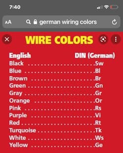
I keep a screenshot of the German wire colors conversion chart on my iPhone (Figure 6).
I mentioned earlier that I truly value the current-flow aspect of the DIN wiring diagram. I’ve encountered situations where the design of the circuit was not quite apparent. Meaning, in simply analyzing the SAE wiring diagram, one couldn’t distinguish a pull-up circuit from a pull-down circuit (Figure 7). As indicated by the RED circle, the diode symbol was the only clue of the direction of current flow. Without that clue (and if there is nothing available in the system description and operation section of the service information), there is no way to know from the diagram alone.
This difference in testing techniques applied to each of those different circuit designs is crucial. If one were to supply a voltage source to a circuit that was thought to be of a pull-up design (but was truly a pull-down design) the circuit would effectively be "shorted to voltage" and the likelihood of circuit and/or component damage is almost certain (ask me how I learned that lesson). I realized quite quickly just how much smoke those engineers can squeeze inside those ECUs! Had I access a DIN wiring diagram, I would've been in much better shape at the end of that workday.
The verdict
All in all, the DIN wiring diagram isn’t all that different from the SAE wiring diagrams. True, the layout is a bit different but the same information is still available. The current-flow aspect of the DIN is quite helpful and the standards set forth by DIN make them pretty predictable, once you’ve grown accustomed to them. The same analysis techniques can be applied to any DIN diagram, across all Euros, due to the standards.I have a challenge for you…the next time you’re faced with an electrical dilemma on a Euro and have access to both DIN and SAE diagrams, troubleshoot the circuitry the way you are comfortable and then apply what you've learned here and utilize the DIN diagram. You'll be surprised just how quickly you will master analyzing them and put another notch in your belt of experience, increasing your confidence as well as your productivity!
About the Author

Brandon Steckler
Technical Editor | Motor Age
Brandon began his career in Northampton County Community College in Bethlehem, Pennsylvania, where he was a student of GM’s Automotive Service Educational program. In 2001, he graduated top of his class and earned the GM Leadership award for his efforts. He later began working as a technician at a Saturn dealership in Reading, Pennsylvania, where he quickly attained Master Technician status. He later transitioned to working with Hondas, where he aggressively worked to attain another Master Technician status.
Always having a passion for a full understanding of system/component functionality, he rapidly earned a reputation for deciphering strange failures at an efficient pace and became known as an information specialist among the staff and peers at the dealership. In search of new challenges, he transitioned away from the dealership and to the independent world, where he specialized in diagnostics and driveability.
Today, he is an instructor with both Carquest Technical Institute and Worldpac Training Institute. Along with beta testing for Automotive Test Solutions, he develops curriculum/submits case studies for educational purposes. Through Steckler Automotive Technical Services, LLC., Brandon also provides telephone and live technical support, as well as private training, for technicians all across the world.
Brandon holds ASE certifications A1-A9 as well as C1 (Service Consultant). He is certified as an Advanced Level Specialist in L1 (Advanced Engine Performance), L2 (Advanced Diesel Engine Performance), L3 (Hybrid/EV Specialist), L4 (ADAS) and xEV-Level 2 (Technician electrical safety).
He contributes weekly to Facebook automotive chat groups, has authored several books and classes, and truly enjoys traveling across the globe to help other technicians attain a level of understanding that will serve them well throughout their careers.