Back to basics for streamlined electrical repairs
Vehicles affected – Various
Tools Used:
· Vehicle information, wiring diagrams
· Scan tool
· Circuit test light
· Power Probe
· DMM
Electrical issues come in many forms. As such, they can be some of the most difficult problems to isolate and repair. With all the electronics on today’s vehicles, electrical issues are not only more prevalent, but challenging and frustrating for even some of the best technicians and diagnosticians in the business, especially if it is an intermittent problem.
In this issue, we’ll discuss some issues that can occur and how to employ a diagnostic strategy using a variety of tools to help determine the root cause of the problem.
Issue 1 – 2014 Jeep Patriot intermittent no crank, no start
This Jeep came into the shop with the customer claiming that the vehicle would not crank intermittently. After interviewing the customer, we discovered there was no real pattern to the issue, and that it had been occurring once every couple of weeks over the past few months. The only repairs that had been done recently to repair the issue was a battery replacement about two weeks ago; and the starting issue has occurred since.
After interviewing the customer, our first step was to test the battery and charging system using our battery/charging system tester. We found no faults and both appeared to be functioning correctly.
Our next step was to scan the Jeep for codes. There were none, but we noticed that many of the monitors had not completed. Incomplete monitors can occur either by someone clearing codes, or a loss of power to the PCM. We decided to monitor the charging system to determine any signs of an intermittent issue. Using our scan tool, we monitored the generator duty cycle and voltage sense.
In the course of monitoring we noticed that the voltage would drop to under 12 volts and the duty cycle would drop to zero. We also noted that the voltage would occasionally rise to around 15 volts, slightly higher than normal.
We suspected some high resistance somewhere in the charging system causing the computer, which controls charging output, to intermittently under and overcharge the system. In our experience, we have found the best way to determine if there is resistance in the circuit is to perform a voltage drop test using a DMM in its voltage Min/Max setting.
A voltage drop test is much more reliable than using an ohmmeter because the results will show the ability of the circuit to deliver enough current. For example, if you were to use an ohmmeter to test a single strand of 16-gauge wire, it will show continuity and zero resistance, just as a length of 16-gauge wire will show continuity and no resistance. If you were to try to carry any load through the singe strand of wire, it would most likely burn, due to its inability to carry an appreciable load.
Performing a voltage drop test will show you the amount of voltage that is available at the circuit when current is flowing. A good rule of thumb for a voltage drop test result is a voltage of less than one-half volt for most circuits. What that really means is that if a circuit is dropping one-half volts and the source voltage is 12.5 volts, the circuit can deliver 12 volts. If the voltage drop shows four volts, the available voltage to the circuit is only 8.5 volts.
We performed a voltage drop test on the starting and charging systems and found a drop of a little over two volts on the ground side. We did notice some minor corrosion on the ground connections for the battery and body grounds. Something to note is this vehicle was originally from Minnesota, so road salts may be a factor in any electrical system corrosion issues.
We cleaned the ground connections and re-tested the system and found the voltage drop readings had returned to normal ranges and after re-scanning, found the charging system functioning normally. The customer has since reported no further starting issues.
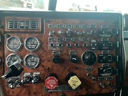
Issue 2 – Intermittent headlamp operation 1999 Peterbilt 379
Intermittent electrical issues can easily be some of the most troublesome problems to diagnose. They can take hours to determine the cause, and many more hours if the vehicle is not experiencing the issue when it’s in your shop. In this case, the truck had lost power to both headlamps on high and low beam, but the tail and marker lights worked.
Compounding an intermittent issue is the fact that this was an older semi-truck with multiple owners; therefore, many hands have been behind the dash and have made modifications and repairs to the electrical system. A once organized routing of wires and connections had turned into a rat’s nest of splices, added connections, and wire taps that made identification very difficult. One significant factor in locating the correct wires to the headlamps is that all the wires behind the dash are white (in some cases) with numbers to identify them. We were unable to see the numbers on many of the wires, making it more difficult to identify the correct ones.
Additionally, correct wiring diagrams are difficult to locate because many trucks of that era were built from the factory and sent to upfitters that finalized wiring connections.
I have found that one of the best strategies to locate a lighting issue is to start at the power side of the circuit, then proceed to both ends of the circuit as directed by the results of each test. What this means is since we have no wiring diagram, start by using a circuit tester at the fuse panel, or in this case the circuit breaker, to determine if there is power at the source.
We connected a Power Probe and found power at the main fuse that supplies power to the switch, which made sense because the tail and marker lights were operating normally. We then tested the switch to determine if there was power on all terminals of the switch. This switch has four terminals, which can in some cases lose power on one side of the switch which could cause the tail and marker lights to work and the headlamps to not. There was power on both sides of the switch when the switch was in the “on” position.
Our next step was to check at the headlamp for power at the connector (there was none). Using the Power Probe, we applied power to the headlamp to make sure we did not have an issue with either a ground or a burned-out lamp. The lamps on both sides of the truck illuminated.
So far, we have determined the switch, fuses, and lamps are all good, so we needed to determine where the flow of current was interrupted from the switch to the lamps. There was a bulkhead connector at the firewall, where we have seen have corrosion issues on similar vehicles. Again, one of the problems was we could not easily identify which wire or which of the three large multi-wire connectors were for the headlamps. Since it is somewhat difficult to observe the lamps and test the bulkhead connector at the same time, we either needed two technicians to test this circuit, or try a little trick I have successfully used in the past.
Set your DMM to the audible tone ohms setting. Disconnect the bulkhead connector and the headlamp power wire at the headlamp. Connect one end of the DMM to the headlamp wire, then touch the other probe to each pin at the engine side of the bulkhead connector. When you hear the tone, you have found the correct wire. Keep in mind, that many heavy-duty trucks use a separate wire to each headlamp, so you should look to see if there is a pin for each side.
Once we found the correct pin, we could now re-connect the bulkhead connector to determine if there was power to the pins going to the headlamps. Our test showed no power and using the Power Probe we were able to determine that when we supplied power to the pins, the headlamps illuminated.
Now that we were able to identify which pins at the bulkhead connector were used, we could back trace them to see where the loss of connection between the switch and the bulkhead was. There were numerous wires behind the dash, and quite honestly, not much room to get to each connector without completely dismantling the dash.
Since headlamps use quite a bit of current, we assumed there would be at least one, and quite possibly two relays for the headlamps. We had previously looked for relays at the fuse/circuit breaker panel near the driver kick panel and even though there were relays located there, none were for the headlamps.
Using the DMM in the ohms mode we checked for resistance from the bulkhead connector to the switch. The circuit tested as “open”, no continuity. Pulling as much of the harness behind the dash as we could, we found a 6-way connector from the headlamp switch to another section of a harness. We tested the wires from the switch and had power on both sides of the connector.
After pulling another section of the dash, we were able to track part of the second harness to an added bank of relays. Using the power probe, we determined that there was no power to the battery + side of the relays.
Tracing the wires from the relay to their power source, we were able to find that someone had used a wire nut to connect wires from a positive source to the battery + relay wire. In my opinion (and per best practices in electrical repair or modifications) wire nuts or wire taps have no place in a professional repair shop. We located three other connections behind the dash that had wire nuts and two that used a wire tap connector. Our recommendation to the owner of the truck was to repair the system correctly by adding a fused power strip and repairing all the incorrect wiring with proper terminal ends and soldered connections.
After the repair, the lamps all worked correctly and as an added bonus, the customer stated the static in the radio was gone, an issue he did not complain about.
The intermittent nature of both these repairs could have been much harder to find had we not started with basic best practice tests and observations that found poor connections and corrosion. After working in this industry for many years and observing hundreds, if not thousands of technicians while teaching classes; I feel that one of the best ways to improve technician performance would be to provide electrical training to them. It is a small investment and for many technicians, it’s their greatest opportunity for improvement.
About the Author

Barry Hoyland
Barry Hoyland has been in the independent aftermarket for more than 45 years as a technician, technician instructor, shop owner, and shop management consultant. He owned and operated a successful Southern California automotive repair center that offers complete auto care and specialized in emission and diagnostic services for over 28 years. Hoyland also owned a company that modified vehicles to perform as emergency response units and mobile command centers, incorporating high-end electronic components into today’s vehicles. Hoyland has experience with all size and types of vehicles including traditional gas, hybrid electric, alternative fuel, and heavy duty diesel trucks.
Hoyland has provided consulting services for many automotive shops, fleets, and government agencies in order to improve their operational efficiencies.
In addition, he has worked with many NHRA drag racing teams as a crew chief on supercharged alcohol and nitro-methane fueled cars and currently serves as a crew chief on a Top Alcohol Funny Car, a Nostalgia Funny Car, and a Nostalgia Alcohol Dragster
Hoyland holds certifications in ASE: A1, A6, A8, and L1, MACS 609, maintains a California Advanced Emission license, and a CDL with endorsements for double and triple trailers, tankers, and HazMat.
When he is not helping to run a shop in the Pacific Northwest, Hoyland travels across the U.S. as an instructor of technical and shop management courses, many of which he has developed.