Vehicle manufacturers and engineers constantly are exploring ways of refining and improving on-board technology. In the search to make lighter, more fuel efficient vehicles, no stone can remain unturned. The home of vehicle power distribution, the “fuse box”, has undergone some significant changes as a result of these efforts. We’ll take a look at what’s new in the fuse box as well as some diagnostic approaches for some of the problems related to power distribution.
Like This Article?
Check out related training at

When you think about how far we have come in terms of electricity and electronics, it is astounding. Growing up, I was in love with the classic Ford Mustang. (OK, I still am). My grandpa had a ’64 ½ convertible, my uncle had a ’66 fastback and after being around those cars, I had to have one of my own. Working in a service station for a few years allowed me to save up some cash and with some help from my grandfather I finally got a red 1967 coupe with a 351 Windsor V8. I remember changing the old glass-style fuses when we restored it, as the fuse box looked a little crusty after many years of service. I think there were a grand total of seven fuses! That little fuse box couldn’t have been more than four inches square.
In 50 years, things have definitely changed. Today’s power distribution centers do a whole lot more than provide a fused pathway. They need to provide power to an innumerable amount of onboard electronic devices and at the same time they have to do the job with less weight.
Fuse Box on a Diet
All of us have known someone who has had success with weight loss. Often times it’s the process of counting every single calorie that leads to their drop in weight. This idea is somewhat similar to what an automotive engineer goes through to make a vehicle lighter. Every single piece on the car contributes to the vehicle’s overall weight. By reducing components and/or the weight of an existing component, we can drop the overall weight of the vehicle and in the grand scheme of things reduce the vehicle fuel consumption. So how do we put a fuse box on a diet? There are several ways that manufacturers are making these changes.
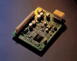
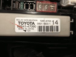
Integration Relays: A few years back, I gave the students in my college electronics class the task of disabling the fuel pump on a 2010 Toyota Camry in order to perform a fuel pressure test. The factory schematic showed what looked to be a four-pin relay in the under-hood junction box. The students came to the conclusion that removing the relay would be the easiest way to disable the pump.
After searching for the relay for about 15 minutes, my students gave up. I knew the feeling because I’ve been there myself. Here was something as simple as a four pin relay and it was kicking their butt. The reality was that they were not looking for a four pin relay at all. Even though the factory electronic wiring diagram shows what looks like a four pin relay, it is actually a transistor, or more likely an integrated circuit (IC). This IC device known as an integration relay takes the place of multiple traditional four-pin relays reducing overall vehicle weight.
After seeing this myself for the first time, I decided to do a bit of digging. I looked up how many four pin relays came on a 2001 Prius as compared to a 2010. The 2001 has 24 relays. The 2010 has relays that can be counted on one hand. The rest are replaced by the integration relay. The integration relay allows for a fairly large reduction in weight of the power distribution center or fuse box. Although it seems like a small step, every ounce counts.
One additional benefit to using a solid state relay as opposed to a traditional relay is that the solid state relay takes far less current to operate. By eliminating 22 relays and replacing them with a solid state IC device there is far less electrical load for the alternator to power. This is a simple way of achieving a power and weight reduction but many manufacturers have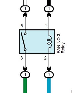
Solid State Power Distribution and Management
All vehicle manufacturers are concerned with the overall power needs of a vehicle. The more loads that are turned on, the more load we put on the alternator. The byproduct of producing a high current output from the generator/alternator is the drag placed on the serpentine belt by the increased magnetic strength of the field winding inside the alternator.
This parasitic drag leads to increased fuel consumption. For this reason, many manufacturers have taken steps to control power management. They are achieving this management through the use of solid state electronic devices. In plain English, they are using ECUs or modules. In some cases, the fuse box itself becomes a module that might need to be programmed/re-programmed when it is repaired or replaced. Let’s take a look at a few of the integrated module/distribution systems, and in particular a few that may cause some problems in your bays.
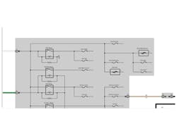
Ford: Smart Power Distribution Junction Box - SPDJB
Ford’s smart junction box (SPDJB) was designed in partnership with its supplier, Lear. According to Lear’s website, Smart Junction Box technology is the main hub in a vehicle's electrical system, controlling and providing power to various electrical features such as power windows, power door locks, lighting (interior and exterior), instrumentation and the audio system. Current Smart Junction Box technology combines fuses, relays, a microcontroller and multiple (circuit board and fret) layers of interconnection into a single integrated assembly. Its job is to provide protection against excessive current loads, typical of a short circuit, by shutting down circuit function.
Problems that can’t be fixed with software updates or programing will typically result in replacing the entire smart unit which can be a costly proposition.
Nissan Intelligent Power distribution Module - IPDM
The IPDM is Nissans answer to power management. It works on the same basic principles as the Ford unit. When working with an IPDM unit, be sure to note that the only serviceable parts of the unit are its fuses.
There is an exception to this with certain Technical Service Bulletins (TSBs) that require you to use a special relay puller to remove the ECM relay on certain years and models. If you are not working with a TSB, do not attempt to remove any relays from the IPDM device. As with any diagnostic routine be sure to check service bulletins when dealing with power distribution problems. Problems with the IPDM that can’t be fixed with software will typically require the replacement of the entire IPDM.
Chrysler: Totally Integrated Power Module – TIPM
The TIPM is Chrysler’s version of smart power distribution. The TIPM is a module and has serviceable fuses and solid state switching with typically no relays.
The TIPM has been the subject of several recent recalls that can result in symptoms including no start the first time, no start at all, a failure to keep running once started, fuel pumps that won't shut off and stalling. Be sure to check service campaigns and TSB’s when working on late MY Chrysler vehicles that are exhibiting these problems.
Diagnostic Strategies
As with any new technology, there will be a learning curve when diagnosing the modern day power distribution center. Basic use of a multimeter and labscope are essential. Without a fundamental ability to diagnose electrical faults, you are in for a painful experience. Many of the faults within the power distribution system will require the use of a scan tool, preferably of the factory variety.
Modern Parasitic Draw Testing
Most of us know by now that disconnecting the battery when performing parasitic draw testing is a bad idea, especially with advanced power distribution technologies. So what is the solution?
• Close doors and lock them with the key fob.
• If the hood is open, be sure to close the latch with a screwdriver. Be sure underhood lamps are out.
• Move keys at least 10 feet away from the car.
• Make sure any Bluetooth device such as a smart phone or Bluetooth headset is removed from the vehicle.
• Wait for a few minutes for the remaining modules to go to sleep. Take your time and go make money fixing something else for now and come back to this when you are done.
The last two bullet points are the ones that I find that most techs are overlooking. If the vehicle uses a smart entry system such as Toyota’s smart key, having the key in close proximity to the car will wake up the modules associated with the entry system and in many cases will turn on the lighting in the vehicle. Toyota suggests keeping the smart key a distance of at least 10 feet from the vehicle when performing parasitic draw testing.
In addition to keys, smart phones and other Bluetooth devices can be a problem. If a Bluetooth-connected device is connected to a system such as the Hands Free Link (HFL) system on Honda vehicles, the Bluetooth device may continue to have communication with the module. Removing smart phones and Bluetooth devices will eliminate the possibility of these devices keeping a module awake.
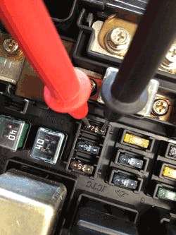
When all preparations are made, it is time to proceed with isolating the circuit that is causing the draw. My method of choice is using my multimeter, set on DC Volts, and voltage drop testing across the top of each fuse until I find one that seems to be flowing current. Let me explain. The only time current is flowing in a circuit is when the circuit is powered or turned on or is shorted and flowing current. Using a meter set on DC volts and performing a voltage drop test provides me with an indication if current is flowing or not. There are charts available that correlate voltage drop to the amount of amperage draw but I don’t rely on them as gospel. I prefer to find the one that seems to be drawing the most. You will find that typically the one with the highest drop is your offender. Once I locate the circuit I will print a power distribution schematic for that circuit. Once I see what the fuse is powering I can start pinpoint testing.
After isolating the circuit, I found that the body shop had removed the courtesy lamp for the rear hatch, as it was staying on. As it turns out, the body shop had the hatch striker installed upside down which was not allowing the hatch to completely close. Once I correctly installed the striker I had it fixed. If only every parasitic draw diagnosis could be this easy! It can be if you are using modern diagnostic techniques.
If the multimeter voltage drop strategy won’t allow you to locate an intermittent draw you may want to enlist the help of a lab scope. Using a lab scope with a low current probe will allow you to see a picture when a particular current draw is occurring. Having a picture of a draw on the screen can be extremely helpful in locating faulty modules.
Constant changes in technology make our job as technicians challenging. Embracing new technology and accepting the challenge will help you make money instead of losing it when it comes to diagnosis.
About the Author

Dave Macholz
Contributing Editor
Dave Macholz is an instructor for the Toyota T-TEN, Honda PACT and general automotive programs at Suffolk County Community College in Selden, NY. He is an ASE CMAT and L1 technician and holds a NY State teaching certification in vehicle repair.