Diagnosing and repairing catastrophic electrical issues
Editor's Note: This article was orginally published May 12, 2017. Some of the information may no longer be relevant, so please use it at your discretion.
Most technicians fall into one of two categories about how to deal with a catastrophic electrical failure (meaning, an electrical issue which causes a fire): They either embrace them or want to run fast and far away from them.
Having a full understanding of what is necessary to perform a complete diagnosis, a comprehensive repair and verifying full functionality will not only help alleviate comeback concerns but will allow you to see the profit-making potential in electrical repair.
The worst electrical failures you will see are fires where the damage is so severe you may not be able to determine the component that started the fire. In these cases, it will be necessary to repair the damage that is visible and test every component that is connected or driven by wiring or other components within the same system. An example of this would be testing any and all solenoids and actuators in the system to assure none of them are shorted or open, and they all function properly.
Step 1: Determine the extent of damage
Determining the extent of the damage will allow you to plan the best way to perform the repair.
If wiring harness damage is extensive, it may be more cost-effective to replace either part or the whole harness, rather than splice in numerous wires. Either way, it will be necessary to use your vehicle information source to access the wiring diagram, component locator and system specifications. The wiring diagram will not only assist in providing information such as wire color, routing and connections, but also details about what other components may have been affected or were the cause of the fire. A component locator will assist you in finding the exact location of components, splices and ground locations in order to perform necessary tests.
System and component specifications will allow you to test individual components to determine if they are functioning and have not been damaged in the fire.
Testing solenoids to assure resistance is within specifications can be done with your digital multimeter. Solenoids should also be tested by removing them from the vehicle and bench testing them to make sure they open and close completely when applying power and ground. These tests can be easily accomplished with a Power Probe which allow you to apply power and ground with the flip of switch.
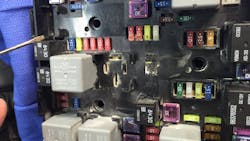
Another critical step in determining the extent of damage is to inspect all connectors. This step starts with a visual inspection of the housing and pins to see if there is any discoloration or deformities. It is also necessary to use a pin tension tool to make sure heat has not weakened the ability of a terminal to form a tight connection to its’ mating pin. These tools are made up of a male pin that has the same diameter of the original connector and is used by sliding it into the female terminal to make sure sufficient drag is felt. Terminals that do not have the correct tension will create heat and a subsequent failure and will require replacement.
Step 2: Repair wiring damage
Take these steps into consideration when forming your repair plan.
Once you have determined the extent of the damage including which parts and wires will need replacing, you will need to determine the best way to perform the wiring repairs. This includes making the determination if a complete new or used harness would be preferred over repairing the existing one.
If connector mating pins require removal from their housing use a connector pin removing tool to remove pins from their mating housings. These tools will allow you to remove the pins without damaging the pin or housing in order to be reused.
Pay attention to the routing of harnesses prior to removal to make sure any spices will be made in areas that are not too close to components or in a curved area.
If only a small area of wiring is damaged, you may be able to cut out the burned sections and use splice connectors and crimp them in. Personally, I am not a fan of crimp splice connectors unless they are the ones that are filled with solder and also use a built-in heat shrink compound. These connections provide a secure water-tight connection that will remain trouble-free.
If there is extensive damage requiring multiple wire splices, it is usually better to remove the harness completely from the vehicle. With the harness removed you will be able to lay it out and install splices in a staggered position. If all the splices are laid out at the same point, the spliced area becomes a much larger diameter than original and may be difficult to work with. With the wiring harness removed from the vehicle it is also much easier to install protective loom and tape.
There are many wire stripping tools available. Some are straight, while others have an angled head in order to facilitate working in tight areas. There are two things to remember when stripping wire insulation: make sure none of the wire strands are removed in the process, and do not strip too much insulation away. If a crimp connector is used, too much or too little insulation will create a poor connection.
When crimping connectors make sure to crimp to the correct torque. Too tight will damage the wire, too loose will create a poor connection.
In my opinion, it is better to solder connections and use a heat shrink protective tubing to create a moisture barrier. Repairing with soldered connections will also minimize the overall bulk of the repair, and at the same time assure a quality repair. Be careful when soldering to not overheat the wire or use too much solder. Doing either will cause the wire next to the solder joint to become too stiff, and the wire may break.
Step 3: Test the system
Once all wiring splices, pins and connections have been repaired it is time to verify functionality.
Instead of connecting the battery and starting the car, connect just the ground cable to the battery. Place a 20A fuse between the battery positive cable and the positive battery post. In most cases a 20A fuse will be more than sufficient to carry enough current to bring keep-alive memory components.
If the fuse blows, there is likely still a short in the system. If the fuse holds, turn the key to the “run” position and recheck. If the fuse still does not blow, remove it and connect the battery cable fully. There are battery connectors available that have a sliding lever which will allow you to disconnect the battery if there is an issue. These can be installed to test if the system is working correctly, and allow you to flip the lever to disconnect the battery quickly if necessary.
Once the vehicle is running, test the charging system, all lights and install your scan tool to verify no fault codes are present. If everything tests okay, road test the vehicle in a drive cycle format which will allow the computer monitors to be completed making sure all those components are functioning correctly.