Piston and Rod Orientation: Get It Right or Pay for It Later
Key Highlights
- Always align the chamfered side of the connecting rod big end next to the crankshaft journal to ensure clearance and proper function.
- Ensure all connecting rods are oriented uniformly, in accordance with engine specifications, to prevent assembly issues and uneven wear.
- Rod bearing tangs are primarily for alignment during assembly; proper bearing crush ensures they won't spin during operation.
- Verify the offset of connecting rods, especially in asymmetric designs, to maintain correct piston positioning and balance.
- Orient oil squirt holes in the rods toward the camshaft or pistons' oiling points to optimize lubrication and reduce wear.
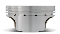
Depending on the engine application, it isn't uncommon for an engine assembler to question the correct orientation of pistons to connecting rods. Ignoring this can result in problems.
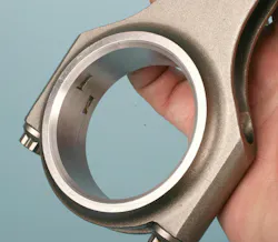
Let's start with connecting rods relative to placement on the crankshaft. The rod's big end may feature a slight chamfer on one side of the rod, with the opposite side featuring no chamfer at all. Always place the side that features a chamfer next to the crankshaft rod journal, which features a slight radius. This allows the chamfered side of the rod to clear the journal's radius. If the rods are designed for use on a crank that doesn't feature a radiused fillet, the rods might not feature a large chamfer on one side. In this case, orient the rod so that the rod bearing tang grooves face outward toward the oil pan rail or face inboard. In either case, orient all rods in the same manner. Some engine designs may specify this orientation.
Rod Bearing Tangs
The upper saddle of the rod’s big end and the rod cap feature short grooves at the parting line area. Contrary to popular belief, these grooves aren't intended to prevent rod bearing “spin” or rotation. In reality, the grooves (and male protrusions on the back of the bearings) simply exist to provide ease of properly aligning and locating the bearings. The bearings are locked in place once the rod cap is fully tightened to the specified clamping load, creating the critical upper-to-lower rod bearing radial crush.
(Note: Some OEM engine designs may use rod bearings that don't feature locating tangs, one example is the Chrysler 3.7L and 4.7L engine family. This is done merely to reduce manufacturing costs. When installing tangless rod bearings, it's up to the assembler to pay attention to properly centering the rod bearings in their respective saddles.)
Rod Offset
Be aware that some connecting rods may feature an offset design. This refers to either the large or small end being slightly offset relative to the centerline of the rod beam. This is done to accommodate engine designs where the centerline of the cylinder bore is slightly offset relative to the rod bearing radial centerline. This offset may be as much as 0.100" or so. During test fitting, it's important to verify that the small end of the rod is centered on the wrist pin (there should be equal spacing between the rod’s small end and each of the piston's pin bosses).
Rod Oil Holes
Some connecting rod big ends may feature a small oil “squirt” hole in one side of the rod's big end. The purpose of this hole is to allow oil to be squirted toward opposing pistons. If the rod's big end has an oil hole, the big end of the rod with the oil hole should be oriented to face toward the camshaft (in a single-cam V engine). Some rod small ends may feature a small oil hole. This is intended to provide additional “splash” oil to the wrist pin.
It should be obvious, but when a piston features valve reliefs, the side of the piston that has these reliefs must align with the location of the intake and exhaust valves. For instance, on a V-platform engine, the reliefs are biased toward the intake manifold. If you're in doubt, pay attention to the piston dome's valve pockets.
Piston Major/Minor Thrust
It may be surprising to some, but piston skirts aren't perfectly round. Each inboard and outboard side of the piston experiences different levels of loading during operation. Actually, the piston skirt area is slightly “barrel” shaped to provide an adequate surface load against the cylinder wall while reducing friction. This surface area is responsible for providing piston stability to minimize rocking relative to the pin axis as the piston moves down from TDC and back up from BDC.
Major thrust
The major thrust face is the side of the piston that receives the thrust on the power stroke. As viewed facing the front of the engine, if the crankshaft is rotating clockwise, the major thrust face is on the left side of the cylinder. On the driver-side bank, major thrust is experienced on the intake side; on the passenger side, major thrust is on the exhaust side. The opposite side of the piston—the minor thrust side—experiences loading force on the compression stroke. The major thrust side is the side of the piston skirt that experiences the majority of thrust loading.
To put this into perspective, during the firing cycle, the load experienced on the major thrust side skirt can be as much as 10 times greater than the load experienced on the minor thrust side skirt. The difference in skirt loading will vary depending on variables such as crankshaft stroke, connecting rod length, and peak cylinder pressures. When the piston is pushed down during the power stroke, it experiences resistance as it attempts to turn the crankshaft. As load increases, the amount of resistance increases. During this resistance, the piston side load is forced to one side—the major thrust side—which places more force (with subsequently increased friction and potential wear) on the thrust side of the cylinder wall. If the piston dome features a reference dot or other mark, it's critical to install the piston with this mark facing the appropriate direction. The mark indicates which side of the piston is intended to face forward.
Minor thrust
As noted earlier, the minor thrust side is forced to the opposite side of the cylinder wall as it moves up on the compression stroke, due to the resistance generated by meeting the air/fuel mixture. The role of the minor thrust side is basically to provide piston stability, with the major thrust side taking the brunt of the cylinder wall contact. As a result, the minor thrust side skirt can be made narrower. This reduces piston weight without sacrificing strength and reduces friction within the bore.
Asymmetric Pistons
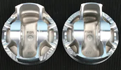
Some pistons feature an asymmetric design, where the major thrust side features a larger skirt, and the minor thrust side features a smaller skirt. Since asymmetric pistons are bank-specific, each piston will be labeled for right or left bank position. The dome may also feature a laser-etched arrow that indicates piston orientation toward the front of the engine. The concept of asymmetric pistons was actually developed back in the 1960s by GM engineers. The design approach is now used by some aftermarket piston manufacturers, primarily targeted at the performance market.
The asymmetric approach provides an additional benefit: increasing piston ring sealing and ring stability. The dedicated major and minor thrust skirt design, coupled with a slightly offset wrist pin, directly addresses ring performance in addition to reduced wall friction.
It's important to note that asymmetric pistons will also feature an offset wrist pin, with the pin centerline biased from zero toward the major thrust side by 0.020". This slight offset tends to balance the piston to accommodate the difference in skirt mass and to compensate for and alter the effect of rod angle, transferring a bit of force away from the major thrust side. This allows the use of shorter, stiffer, and lighter wrist pins.
Reverse-Rotation Engines
Some engines (some marine applications, for example) feature a reverse-rotation design where the crank rotates counterclockwise when viewed from the front of the engine. In those applications, the connecting rods are installed similar to a clockwise-rotation engine, maintaining the chamfered side of the rod big end facing the journal's radiused fillet. However, if the pistons feature an offset pin, the piston must be installed “backwards” relative to installation in a clockwise engine. The pin offset is still biased toward the major thrust side of the piston. In a clockwise-rotating engine, the major thrust side is at the intake side on the left (driver) bank and the exhaust side on the right (passenger) bank. In a reverse-rotation engine, the thrust sides are opposite: the major thrust side will now be at the exhaust side of the left bank and the intake side of the right bank. If the pistons are symmetric (not asymmetric) and don't feature an offset pin location, piston orientation won't matter, as long as the valve pockets (if any) are located appropriately to the valve locations.
About the Author
 Mike Mavrigian
Mike Mavrigian
Motor Age Editor
Mike Mavrigian has written thousands of automotive technical magazine articles involving a variety of specialties, from engine building to wheel alignment, and has authored more than a dozen books that crisscross the automotive spectrum. Mike operates Birchwood Automotive, an Ohio shop that builds custom engines and performs vintage vehicle restorations. The shop also features a professional photo studio to document projects and to create images for articles and books.