GDI Fuel Systems: What You Need to Know About Modern Fuel Injection
Key Highlights
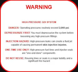
- GDI systems operate at pressures exceeding 2,000 psi, requiring specialized knowledge of high-pressure components and safety procedures.
- Verifying the low-pressure side is essential before diagnosing high-pressure issues to prevent unnecessary component replacement.
- Mechanical failures often involve camshaft pump interface wear or internal leaks, which can cause fuel dilution and engine damage.
- Electrical sensor skewing can lead to incorrect pressure readings, causing over- or under-fueling and drivability problems.
- Proper handling and replacement of high-pressure lines and seals are critical, as reusing these parts can lead to leaks and safety hazards.
From the Start
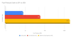
Not long ago, a standard fuel pressure spec was a mere 5–8 psi on carbureted engines. When fuel injection hit the scene, those numbers climbed toward 60 psi. Today, however, Gasoline Direct Injection (GDI) is common, with systems operating at pressures that routinely exceed 2,000 psi.
This massive jump in pressure changes everything. We are now dealing with injectors exposed to the raw heat of the combustion chamber, one-time-use high-pressure lines, and specialized sensor arrays. Troubleshooting these systems requires a shift away from “code chasing” and toward structured diagnostics that combine high-speed data with mechanical testing to find the root cause.
The Components
Understanding GDI requires shifting focus from simple electrical circuits to a marriage of high-speed electronics and heavy-duty mechanics. To diagnose the system effectively, it helps to understand the specific roles of the components on the high-pressure side.
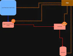
1. The Low-Pressure Lift Pump
Everything starts here. The high-pressure pump cannot pull fuel from the tank; it must be “fed.” Most modern GDI systems utilize a Pulse Width Modulated (PWM), returnless lift pump. Before condemning any high-side component, you must verify that the low side is delivering the specified feed pressure (often in the 50–80 psi range, and up to around 100 psi on some applications) and sufficient volume.
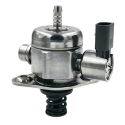
2. The High-Pressure Fuel Pump (HPFP)
The HPFP is a mechanical, single-piston, positive-displacement pump, usually mounted to the valve cover and driven directly by the camshaft. It is important to remember that this pump is a fixed-displacement device: it moves a set volume of fuel into the rail each stroke, and the pressure you see is the result of that volume entering a mostly sealed system at a given engine load.
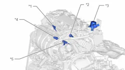
3. Camshaft Lobe & Roller Follower
The mechanical link between the engine and the fuel system is a specialized tri-lobe or quad-lobe section of the camshaft. Between the cam and the pump sits a lifter or roller follower. This is a high-friction environment; any lubrication failure or oil dilution quickly leads to galling or flattening of the lobe, which reduces pump stroke and results in loss of high-side pressure.
4. Volume Control Valve (VCV)
The VCV is a solenoid integrated into the HPFP and commanded by the PCM. Unlike an old-school regulator that bleeds off excess pressure, the VCV regulates rail pressure by controlling timing. By precisely timing when the pump’s internal intake valve closes during the piston’s upward stroke, the PCM determines exactly how much fuel is compressed into the rail.
5. Fuel Rail Pressure (FRP) Sensor
The FRP sensor is the PCM’s feedback loop. Because the PCM relies heavily on this sensor to determine VCV timing, a skewed sensor, one that remains within its electrical operating range but reports inaccurate pressure, is one of the most difficult ghost issues to diagnose. If the sensor reports 500 psi when the rail is actually at 2,000 psi, the PCM will continue to command maximum volume, maintaining a severe over-pressure and rich condition because it believes pressure is still low.
6. GDI Fuel Injectors
These are not standard PFI injectors. They are seated directly in the combustion chamber and must overcome cylinder pressure to deliver fuel. They operate at significantly higher voltages than traditional port injectors, often in the 60–90V range using a boosted driver circuit, to ensure the pintle opens against high rail pressure. They are also subject to extreme heat and carbon build-up that can distort spray patterns over time.
7. High-Pressure Lines and Seals
In the GDI world, many high-pressure components are one-and-done. The stainless-steel high-pressure lines use crush-style flare fittings that deform to create a seal when first torqued. Reusing these lines, or the Teflon seals on the injectors, is a major liability; at 2,000 psi, a compromised seal is not just a leak, it is a torch.
Common Failure Points
In the GDI environment, failures are rarely subtle. Because of the extreme pressures and tight tolerances, a small mechanical or electrical deviation quickly shows up as a drivability concern or a limp-home mode. Once you understand the major components, the next step is recognizing how they fail in the real world.
1. Mechanical Failure: The Camshaft-to-Pump Interface
One of the most frequent mechanical failures is not the high-pressure pump itself, but the interface where it is driven. The pump relies on a dedicated tri-lobe or quad-lobe section of the camshaft to actuate its piston. If the roller follower or bucket lifter between the cam and the pump fails, it creates a metal-on-metal grinding scenario that quickly wears down the cam lobe, flattening it and reducing pump stroke. The result is a significant loss of fuel volume, typically manifesting as loss of power under high load or a P0087 (Fuel Rail Pressure Too Low) code. Technicians must resist the urge to simply swap the pump; it is vital to inspect the cam lobe with a borescope or by physical removal, because a flat lobe will cause a brand-new pump to fail immediately.
2. Internal Leaks: Fuel Dilution and Crankcase Contamination
Internal leaks within the high-pressure pump present a different, often more dangerous, set of challenges. The HPFP contains an internal piston seal designed to separate high-pressure gasoline from the engine’s oiling system. When this seal breaches, high-pressure fuel is forced directly into the crankcase, leading to rapid fuel dilution of the engine oil. This thins the oil, which can cause catastrophic bearing damage and accelerated wear on the very cam lobes that drive the pump. High-level indicators of this failure include a rising oil level on the dipstick, a strong scent of raw gasoline in the oil, and skewed fuel trim data as the PCV system pulls excessive fuel vapors into the intake manifold.
3. Electrical Failure: The “Skewed” FRP Sensor
Electrical failures often center around a skewed Fuel Rail Pressure sensor, which can be a diagnostic nightmare because the PCM is only as good as the data it receives. If a sensor’s calibration shifts, reporting 400 psi when the rail is actually at 1,200 psi, for example, the PCM will command the VCV to maximum output, driving the system into a massive over-pressure and rich condition. Because the PCM believes the bad data, the scan tool may show desired and actual pressures perfectly matched even while the engine is producing black smoke, rich misfires, and wildly negative fuel trims.
4. Chemical Impact: Carbon Build-Up and Injector Deposits
Carbon build-up or “coking” on injectors is a major chemical and environmental concern. Because GDI injectors are seated directly inside the combustion chamber, they are subjected to intense heat and the direct byproducts of every combustion event. Over time, deposits form on injector tips, disrupting the ultra-precise spray pattern required for proper atomization, which leads to poor fuel–air mixing, cold-start misfires, soot-fouled plugs, and a noticeable drop in fuel economy. This environment makes the use of high-quality, top tier fuels a technical requirement for GDI longevity rather than just a marketing suggestion.
Diagnostic Procedures
Knowing the common failures is only half the battle; the following procedures turn that knowledge into an efficient diagnostic workflow. In a high-pressure, high-liability system, process is everything.
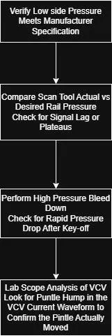
1. Low-Side Verification: Establishing the Foundation
Before diving into high-pressure data, the technician must confirm the health of the low-pressure lift pump. Because the HPFP is a positive-displacement pump, it cannot generate the required rail pressure without a consistent feed of volume and pressure from the tank, typically in the 50–100 psi range depending on the application. Many modern systems use a PWM returnless setup where the PCM adjusts pump speed based on load, so verifying this foundation with a mechanical gauge and scan tool PIDs is “Step Zero” of GDI diagnostics; skip it, and you risk condemning an expensive high-side pump for a simple delivery issue from the tank.
2. Scan Data Analysis: Desired vs. Actual Pressure
Once the low side is verified, the first stage of electronic diagnostics involves graphing “Desired Fuel Rail Pressure” against “Actual Fuel Rail Pressure” during a test drive. In a healthy system, these two lines should mirror each other closely, even under heavy acceleration. If the actual pressure plateaus or lags significantly behind the desired value, it indicates a volume deficiency; this data helps the technician differentiate between a mechanical pump failure, a restricted feed, or a VCV that is not responding correctly to PCM commands, allowing for a data-driven decision before any components are removed.
3. The High-Pressure Bleed-Down Test
Diagnosing issues like hard starts or rich codes at idle often requires a high-pressure bleed-down test. By monitoring the FRP sensor after key-off, you can observe how well the system holds pressure. A rapid drop usually points to one of two culprits: a leaking injector dripping fuel into the combustion chamber, or a failing check valve within the HPFP that allows pressure to bleed back to the low side. It is critical to account for temperature during this test; as a hot engine cools, the fuel in the rail naturally contracts, causing a slight, slow pressure drop that is normal and should not be misdiagnosed as a leak.
4. Advanced Scope Testing: Seeing the Truth
When scan data is inconclusive, the lab scope becomes the ultimate diagnostic tool for verifying the mechanical movement of GDI components. By current ramping the VCV, a technician can see the “pintle hump” in the waveform, a small change in current that provides physical proof the valve moved. Similarly, scoping the FRP sensor signal allows you to analyze the voltage ripple, the small pressure pulses created by each stroke of the HPFP; if these pulses are uneven or missing, it confirms a mechanical issue with a specific cam lobe or an internal pump failure that a scan tool, which averages data, would never reveal.
Shop Essentials and Safety
All of this technical knowledge has limited value if the work is not done safely and with an eye toward liability. Working at 2,000 psi removes much of the margin for error found in traditional port-injection setups, making safety protocols and proper component handling non-negotiable.
1. Systems Under Pressure: The Danger of Skin Injection
The most critical safety consideration in GDI service is the sheer magnitude of the pressure involved. At 2,000+ psi, a pinhole leak is not just a fire hazard; it can create a focused fluid jet capable of causing “skin injection” injuries, where fuel is forced through the skin into underlying tissue, leading to localized toxicity and potential necrosis. Technicians must follow manufacturer-specific procedures to depressurize the system, typically by pulling the fuel pump fuse or using a scan tool command while the engine is running—before loosening any high-pressure fittings.
2. One-Time Use Components and Liability
In the GDI world, “one-and-done” is the rule for high-pressure hardware. Stainless-steel fuel lines and injector seals are designed to deform and “crush” during the initial torque sequence to create a gas-tight seal at extreme pressures. Reusing these lines or Teflon injector seals is a significant liability; even if a reused line does not leak on the initial test drive, the compromised flare can fail under the heat and vibration of daily use, so new high-pressure lines, fuel rail bolts, and seal kits should always be sourced to ensure repairs are both safe and effective.
3. The “Sniff Test” and Oil Maintenance
Because HPFP internal seal failures are common causes of fuel dilution, every GDI diagnostic should start at the dipstick. A failing internal piston seal will dump raw gasoline into the crankcase, thinning the oil and destroying its lubricating properties. If the oil level is suspiciously high or carries a sharp scent of gasoline, the pump must be replaced along with an immediate oil and filter change, because neglecting this step can lead to premature bearing failure or “ghost” rich-condition codes as the PCV system draws fuel-laden vapors into the intake.
Conclusion
The jump from roughly 60 psi to 2,000 psi has fundamentally changed how fuel system repair must be approached. In this high-stakes environment, the “parts cannon” is not just outdated and expensive, it is dangerous. To stay profitable and protect customers, shops must adopt a diagnostic mindset rooted in data and physical verification. By systematically verifying the low-side foundation, leveraging scan tool data to compare desired versus actual pressure, and using the lab scope to “see” the mechanical movement of valves and pumps, technicians move from guessing to knowing. GDI high-pressure systems are not just another set of parts; they are a precision environment that rewards disciplined diagnostics and elevates the craftsmanship of modern automotive repair.
About the Author

Noah Nelson
Technical Editor | Motor Age
Noah Nelson is the Technical Editor for Motor Age Magazine. As an ASE Master Certified Automotive Technician (A1–A9) with 25 years of hands-on industry experience, Noah specializes in advanced electrical systems, vehicle communication networks, and physics-based diagnostic workflows. He is currently documenting his pursuit of the prestigious ASE/AutoCare Association World Class Technician registry.