Removing Resistance From Your Routine: Why Voltage Drop Testing Reveals Hidden Electrical Faults
Resistance measurements can offer a quick path to successful diagnosis, or a long walk home with your tail between your legs. It's all in what you make of it. I remember a time when a coworker was bitten by the results of a resistance measurement, not yet hip to the fact that testing an unloaded circuit could leave a few stones unturned. This simple misinterpretation of data cost the shop nearly $1,000, and the embarrassed technician a gauntlet of ridicule for days to follow.
It's unfortunate that the lessons we tend to learn in our corner of the world are usually achieved only in real-world conditions and tend to be either costly, embarrassing, painful, or often a combination of the three.
So It Begins
I recall it like it was yesterday, my first real purchase of diagnostic equipment. I was 18 years old and was in the early stages of Specialized Electronics Training put on by GM Automotive Service Educational Program. I had just purchased my new Fluke 87A.
We set our DVOMs to "resistance/continuity,” like excited toddlers attracted to the audible feedback, and shunted the test leads together. More than 20 meters rang out in harmony, like bikers twisting the throttles at a stoplight. I'm not sure why that was exciting to us, but it made me feel like I was progressing toward being a real professional technician.
Days into the course, and we were implementing the DVOM in many facets. As we created and tested against an assortment of circuit combinations, the information our instructor passed along to us became clearly evident as the tests were conducted.
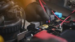
One of the test results most easily seen and interpreted was a test for resistance across a cigarette lighter circuit. The resistance through the circuit was measured with the circuit in both an "open" and a "closed" state. These easy-to-interpret test results gave confidence that the test was a reliable one to carry out in a testing routine. Perhaps a little too much confidence (Figure 1).
The Application of Ohm's Law
One of the most basic laws of electricity that all technicians must grasp is Ohm's law. Cutting past the technical jargon that many get hung up on (and discouraged by), Ohm's law describes the relationship between:
- Voltage (electrical potential/electrical pressure)
- Amperage (electrical current/flow of electrons through a circuit)
- Resistance (the opposition to that flow of electrons)
Regarding the direct current circuitry found in the vehicles we see each and every day, there are characteristics that we learn to become familiar with and rely heavily upon, regarding Ohm's law.
- When resistance remains unchanged, an increase in voltage (electrical pressure) will create more flow of electrons (more current). Just like a decrease in voltage will reduce the flow of electrons.
- If the voltage remains unchanged, an increase in resistance will reduce current flow. Of course, the opposite holds if the amount of resistance decreases.
- If the current remains unchanged and resistance increases, the voltage must have increased as well. Again, the opposite holds.
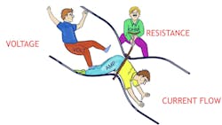
Simple concepts like these are easy to see, especially when staring at pictures like this helpful cartoon (Figure 2). I think this is a huge reason why so many rely so heavily on resistance measurements.
The good news is that when resistance measurements fall outside of specification, a fault is present and is being displayed by the ohmmeter. The problem is that not all faults will be visible with an ohmmeter.
The Fuel Pump That Couldn't
A real-world example from what I'm describing is one from nearly 15 years ago. A good friend of mine is an excellent nuts-and-bolts type of technician; he can repair anything. But when it comes to diagnostics (particularly electrical troubleshooting), he concedes to his shortcomings.
A 2006 Honda Odyssey was towed to the shop with a complaint that the engine lost power while driving. The engine stalled on the side of the road and would then only crank/no-start.
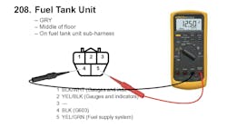
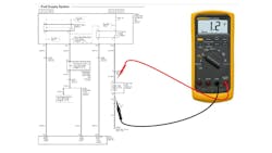
Upon placing the vehicle in the work bay, the tech quickly determined the fuel pump was not functioning. After removing a panel to access the fuel pump, the connector was removed from the pump assembly, and the technician tested for available voltage and ground. As the key was cycled, full electrical potential (about 12.5V) was present during the 2-second prime, and at about 10V while the starter was energized to crank the engine (a normal and expected result) (Figure 3).
Following his test results, the technician removed the fuel pump to ensure fuel was present in the tank. Upon confirmation, he then replaced the fuel pump. The engine failed to start, and again, the fuel pump was not functioning. Performing the same test, the technician confirmed sufficient voltage and ground availability at the terminals of the disconnected fuel pump connector.
Confused, the technician reached out for help (realizing the limitations of his knowledge base). From afar, it was suggested to him that the test he performed was not necessarily revealing of a fault and that a dynamic test would be more suitable. A bit perplexed, he then decided to measure the resistance of the open circuit, again only to find the results still pointing to a faulty fuel pump motor.
At this point, I stopped over to offer assistance. Instead of measuring for available voltage and ground at an unmated connector, I instructed him to leave the connector mated as it would be during normal operation. I then suggested the circuits be monitored while attempting to operate the pump. This is what we refer to as a voltage drop test. A back-probing or pierce-probing of both circuits allows this test to be conducted.
Doing so allowed the voltmeter (not the ohmmeter) to display the amount of voltage "used up" across the intended load (the fuel pump). In a normally functioning circuit of this design, the fuel pump should use almost all of the available voltage across it. Armed with this anticipation, the expected meter reading (if the circuit was healthy) should have been in the neighborhood of 12.5V. The actual voltmeter reading displayed about 1.2V. The results displayed that the fuel pump only used up about 1.2V. That meant 11.3V was being wasted elsewhere. An insufficient ground, insufficient voltage supply, or high-resistance that is only revealed when the circuit is loaded/attempting to operate (Figure 4).
Ohmmeter Construction
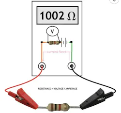
The reason the ohmmeter isn't as reliable a tool as many make it out to be is how it functions to determine resistance. The internal circuitry of the meter (when measuring resistance) leverages the meter's battery source to place a small electrical current (of a known value) on the circuit being measured. The resistance of the circuit being measured will create a voltage drop (just as Ohm's Law prescribes). It's this measured voltage drop that the ohmmeter will correlate to a resistance value, for display.
In essence, the ohmmeter uses the equation R=V/I (meaning, the resistance is equal to the resulting quotient of "measured voltage drop, divided by the known current flow used by the ohmmeter") (Figure 5).
This is not to say that the results of a test conducted with an ohmmeter are inaccurate. It's simply to say that we must always be cautious of resistance measurements that meet the specification. We must always realize the limitations of the test we are performing and the limitations of the tools used to display those test results.
A test that results in a "failure" can be trusted (if conducted properly). However, a test that results in a "pass" may still have an underlying fault that might only be revealed under more loaded conditions. These conditions typically require the circuit to be operated as intended, under dynamic conditions.
There is no better way to accomplish this than attempting to operate the circuit naturally and measuring for voltage drop (across the intended load) instead of an open-circuit resistance measurement with an ohmmeter. However, there will be situations where that may not be possible.
For instance, if that same fuel pump circuit fault was a result of a truly faulty pump (an open or extremely high internal resistance), current flow would be insufficient to load the rest of the circuit properly. Meaning, there may be a subsequent fault in the circuit supporting the operation of that pump, but there would be no way to load the circuit dynamically simply by operating the circuit as intended, because the circuit doesn't work at that moment. This would require an outside source to adequately conduct a loaded voltage-drop test.
The Loaded Voltage-Drop Test
The loaded voltage drop test is typically conducted in a scenario when the circuit cannot be completed naturally (like when a relay closes, a transistor latches, or a button is depressed to close a switch contact).
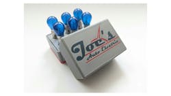
Leveraging a device like this one from Joe's Auto Electric allows you to simply combine the operation of anywhere from one through six bulbs simultaneously to load the circuit being tested. Each bulb pulls about 2.5 amps of current. Where four bulbs operating in parallel will pull about 10 amps of current, all six bulbs, in parallel, will pull nearly 15 amps. The idea is to closely match the "normal load" that the circuit operates with when functioning as it should (Figure 6).
For example, when testing a tail lamp bulb circuit, only one bulb would need to be used to adequately load the supporting circuit on the suspect vehicle. However, a fuel pump would require the implementation of all six bulbs operating in parallel to load the supporting circuit adequately.
To use too small a load (like using only one bulb, when four should be used) may mean that the test you conduct shows the circuit capable of operating the smaller load. The voltage drop of that single test bulb would glow brilliantly. Even if the circuit was compromised, you would never know it. If the circuit was tested adequately (with the four bulbs operating), they would easily reveal an underlying fault in the suspect supporting circuit of the intended device.
The irony in all of this is that even the ohmmeter (used to measure resistance) is truly conducting a voltage-drop test. I think that should be a sign that we need to be testing dynamically when evaluating components and the circuits they reside in. The proof is in the pudding.
When a properly conducted resistance test fails to show a problem, it's simply because the ohmmeter uses such a small amount of current to carry out that test. This insufficient current amount is not enough of a load on the suspect circuit to flush the fault to the surface and reveal it.
It's no different than sitting in a chair and having your blood pressure/heart rate monitored. An underlying fault may be present, but until you are running on a treadmill at a steep grade, that health condition may go undetected. Replace an inoperable component without properly load testing the supportive circuitry, and the results may just give your boss heart failure.
So, to revisit the point of my sharing this information, the resistance test is one that is easily conducted and can be reliable when faults are revealed. However, the low current used by the ohmmeter to conduct the test can inadequately load the circuit and leave many faults undetected.
Begin to set the resistance test aside, and instead, perform a voltage-drop test across the intended load of the suspect circuit. If the circuit cannot be operated due to a faulty component, implement the loaded voltage-drop test (like described above). In either case, if your results display nearly the source voltage, rest assured of two things. Your supporting circuit is healthy, and the fault is lying right between your two test leads. If the test results across the intended load are sub-par, there is a supply issue on either the voltage-side or ground-side of that intended load. Now, go find it!
Please be reminded that all new tools and testing techniques take time and a willingness to practice. Do so on known-good circuits and then conduct the same test on a suspect one. You'll be delighted to learn just how much more accurate and efficient you will become. This, I can promise you!
About the Author

Brandon Steckler
Technical Editor | Motor Age
Brandon began his career in Northampton County Community College in Bethlehem, Pennsylvania, where he was a student of GM’s Automotive Service Educational program. In 2001, he graduated top of his class and earned the GM Leadership award for his efforts. He later began working as a technician at a Saturn dealership in Reading, Pennsylvania, where he quickly attained Master Technician status. He later transitioned to working with Hondas, where he aggressively worked to attain another Master Technician status.
Always having a passion for a full understanding of system/component functionality, he rapidly earned a reputation for deciphering strange failures at an efficient pace and became known as an information specialist among the staff and peers at the dealership. In search of new challenges, he transitioned away from the dealership and to the independent world, where he specialized in diagnostics and driveability.
Today, he is an instructor with both Carquest Technical Institute and Worldpac Training Institute. Along with beta testing for Automotive Test Solutions, he develops curriculum/submits case studies for educational purposes. Through Steckler Automotive Technical Services, LLC., Brandon also provides telephone and live technical support, as well as private training, for technicians all across the world.
Brandon holds ASE certifications A1-A9 as well as C1 (Service Consultant). He is certified as an Advanced Level Specialist in L1 (Advanced Engine Performance), L2 (Advanced Diesel Engine Performance), L3 (Hybrid/EV Specialist), L4 (ADAS) and xEV-Level 2 (Technician electrical safety).
He contributes weekly to Facebook automotive chat groups, has authored several books and classes, and truly enjoys traveling across the globe to help other technicians attain a level of understanding that will serve them well throughout their careers.