Turbo Diagnostics: How Boost, Airflow, and PCM Strategy Work Together
Turbocharged engines are now part of everyday repair work. They show up in compact cars, crossovers, pickups, and performance models from every manufacturer. The technology is no longer reserved for a specialty corner of the shop. It’s something technicians deal with constantly, and understanding how these systems operate is essential for accurate diagnostics. A turbocharger does not look complicated at first glance. It uses the flow of exhaust gas to spin a turbine that drives a compressor, which forces more air into the engine. The goal is simple. Increase the density of the intake charge so that more oxygen is available for combustion. When you increase the amount of oxygen entering the cylinders, the engine can burn more fuel and make more torque without needing a larger displacement. That basic explanation is correct, but the systems supporting a turbocharger are complex and sensitive to even minor faults.
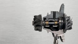
A modern turbocharger works under extreme conditions. The turbine can spin beyond 300,000 rpm. The temperature at the turbine inlet can exceed anything else in the engine compartment. The bearings rely on a thin, stable film of clean oil. The compressor must move large volumes of air while maintaining efficiency. The wastegate control or variable geometry system must constantly adjust to match and maintain the PCM's desired boost pressure level.
The PCM monitors a wide range of parameters continuously, in order to deliver the correct amount of compressed air and fuel to the engine's cylinders. When any part of this relationship drifts out of range, the effects can be immediate. The driver may feel a lack of power, illuminated MIL, poor throttle response, surging, hesitation, or a change in engine sound. A diagnostic trouble code may or may not be stored. This is why a structured approach is essential.
Sensor Rationality
A good starting point is to confirm that the engine's intake system pressure-sensing information being fed to the PCM is accurate. Before a road test or a hands-on mechanical inspection, always begin with a rationality test. This simple check ensures that the Manifold Absolute Pressure Sensor, the Barometric Pressure Reading, the Exhaust Gas Recirculation Pressure Sensor, and any dedicated Boost/Charge Air Pressure Sensor all match each other when the key is on, and the engine is off (KOEO). You want these sensors to be very close to each other during KOEO, and in most cases, the pressure difference should not be more than about 0.5 psi. If these KOEO pressure readings are not within this spec, the PCM cannot accurately figure out engine load and cannot make correct decisions about wastegate control or fuel delivery. A small error in one of these sensors can lead the PCM to believe there is an underboost or overboost condition even when boost is normal. Starting with this check prevents wasted effort later in the diagnostic routine.
Light Throttle Behavior
Once those values pass inspection, the next step is understanding how the turbocharged system behaves during normal driving. Light throttle behavior is often overlooked, yet it provides valuable information about airflow, wastegate control, and the general health of the turbocharger. During slight acceleration, the MAP value should rise above barometric pressure, and the mass airflow should increase predictably. The wastegate should begin to modulate, but should never be near full command at this stage. If the PCM is commanding the wastegate harder (higher duty cycle) than it should during low load, or if the mass airflow is weaker than expected, something is not right, because the duty cycle should stay low at light throttle and any rise in that number can point to an air leak, an airflow restriction, a sticking actuator, or a compressor problem, and this light-throttle data will reveal the issue long before it becomes dramatic.
Wide-Open Throttle and Boost Control
With that information recognized, a full-throttle road test becomes more meaningful. During wide-open throttle, the PCM commands the turbocharger to reach a specific boost target, shown on the scanner as the Desired Boost Value. When everything works correctly, the Actual Boost Value will track this commanded value closely. The gap between desired and actual boost values should remain tight; they should almost mirror each other. When the system cannot meet the commanded/desired boost pressure, the system is in an underboost condition. This condition often sets the P0299 code, which many techs are familiar with. During this underboost situation, the PCM increases the wastegate's duty cycle command to force more exhaust energy into the turbine, spinning the compressor faster. If the wastegate duty cycle value is already near maximum and the boost stays low, the system is either leaking air (quite common), restricted, or unable to spin the turbocharger. If the wastegate command is dropping but the boost level keeps climbing past the desired value, the system is overboosting. When this happens, the PCM will set an overboost DTC, such as P0234, because it can no longer control the turbocharger, and other engine systems may become active to protect the engine from damage. The PCM can reduce spark timing, close the electronic throttle, limit fuel delivery, shut off boost control, or place the engine in a reduced power mode to keep cylinder pressures from climbing too high during an overboost event. These patterns reveal most turbocharger faults before any mechanical work is done.
Wastegate Function and Control Methods
Wastegate function is central to boost control. Each manufacturer does it a little differently, but the idea is always the same. The wastegate manages how much exhaust energy is allowed to drive the turbine. At idle, the wastegate stays closed so the turbo is ready to respond, and as load increases, the PCM moves it as needed to hold the commanded boost. This keeps the system from falling into underboost or climbing into overboost. If the wastegate hangs open, too much exhaust bypasses the turbine, and the turbo will spool slowly with low boost output. A wastegate that is stuck closed can easily cause an overboost condition, which can trigger engine protection mode if equipped and limit engine power.
Many manufacturers still use vacuum-actuated wastegates. These systems introduce another potential failure point because the vacuum supply must be strong and consistent. A weak vacuum pump, a restricted line, a leaking vacuum reservoir, or a leaking control valve can limit wastegate movement. This results in the wastegate appearing functional, but it may not be able to travel far enough to control boost effectively. Understanding the relationship between command, position, and vacuum supply is important in these systems. A pressure-actuated wastegate relies on boost pressure fed directly to the actuator to control how far the wastegate opens. Any leak in this hose or control path will change the pressure the actuator sees and can cause the wastegate to open too early, too late, or not at all.
Some engines use electric wastegate actuators. These units provide precise control and faster response and are often found on smaller displacement turbocharged engines where accuracy matters. Electric actuators require proper calibration after replacement, and many manufacturers include a dedicated adaptation or relearn procedure. Skipping this step is a common cause of repeated underboost or overboost complaints. Manufacturers such as BMW, Volkswagen, Audi, Hyundai, and Stellantis all need specific wastegate calibrations after service. Many electric turbo wastegate actuators will run a self-test during engine shutdown, and the technician can often see the learned positions and commanded values change as the actuator sweeps through its calibrated range.
Another major design is the variable geometry turbocharger. This is common on diesel engines and is starting to appear on some gasoline applications. A Variable Geometry Turbocharger uses a ring of movable vanes to change the flow characteristics of the exhaust entering the turbine housing. At low speeds, the vanes close in, which accelerates the exhaust and helps the turbocharger spool quickly. At higher loads, the vanes open, allowing more exhaust flow while preventing excessive backpressure. The advantage is strong low-end torque and smooth power delivery. The challenge is that the mechanism is sensitive to soot accumulation, corrosion, and mechanical wear. When the vanes cannot move freely, the turbocharger becomes slow to respond or cannot reach the desired boost. Manufacturers such as Ram, Ford, and GM have specific actuator relearn routines after VGT turbocharger or actuator replacement or cleaning. These procedures ensure that the PCM understands the fully open and fully closed positions of the vanes. A technician must always perform these calibrations, or the turbocharger will not operate correctly. Like the non-VGT design, the VGT wastegate will perform the same calibration tests when the engine is shut off, sweeping through its range so the PCM can confirm the learned positions.
Oil Supply: The Lifeblood of Turbocharger Health
A steady, clean, filtered oil supply is one of the most important factors in turbocharger life. The turboshaft that connects the turbine and compressor assemblies rides on a very thin film of oil. In a fully-floating bearing system, the oil forms a wedge that suspends the shaft and prevents metal-to-metal contact. Because the turbocharger's rotational speeds are so high, any interruption or contamination in the pressurized oil supply can potentially damage the bearing surfaces. Restricted oil feed lines, contaminated oil, clogged filters, and coked oil passages all contribute to turbocharger failure. Many modern turbochargers include narrow-feed passages that are easily restricted when oil quality drops. Some manufacturers specify replacing the oil feed line during turbo service to prevent contaminants from entering a new turbocharger. BMW, Volkswagen, Audi, and some GM and Ford applications include this requirement.
A turbocharger's compressor wheel can feel slightly loose when the engine is off because the bearings are not supported by oil pressure, and this small amount of movement is normal and not usually a concern. Once the engine is running, the pressurized oil lifts and centers the rotating assembly, taking up that clearance and allowing the turbo to spin smoothly at high speed.
Oil Leakage and Pressure Balance
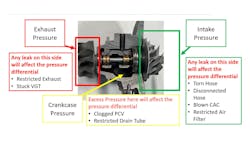
Oil leakage is another area of confusion. Many technicians assume that oil found in the compressor housing or the turbine housing indicates a failed turbocharger. Turbochargers rely on dynamic sealing and pressure differentials, and don't use traditional oil seals. Turbo seals function similarly to piston rings, employing precisely matched metal rings to contain the lubricating oil. They depend on pressure differentials within the turbocharger to retain oil within the bearing housing while preventing the boost pressure and exhaust gases from entering. The pressure in the compressor housing, turbine housing, and center housing must remain balanced. If the crankcase ventilation system becomes restricted or if the intake system has a blockage, the pressure can shift, and oil will move to an area where it normally does not belong. A restricted air filter, a blocked drain tube, a collapsed intake duct, or a sticking variable geometry mechanism can all create pressure imbalances. Replacing a turbocharger without diagnosing the pressure imbalance will result in another failure. Oil control must be viewed as part of the system rather than a fault separated from airflow and pressure.
Bypass and Diverter Valve Control
Airflow management continues with the bypass or diverter valve. When the throttle closes during boost, the pressure trapped between the turbocharger and the throttle plate must be relieved. If it is not relieved, the turbocharger may stall briefly as the airflow reverses direction. This causes noise, surging, hesitation, and in worst case scenario, turbocharger damage. The bypass valve either vents or recirculates this trapped pressurized air. When it leaks or reacts slowly, the engine may struggle to reach commanded boost or might surge when the throttle is lifted. Data logging helps here because the mass airflow and manifold pressure drop sharply when the bypass valve activates. The technician can compare throttle position, bypass valve command, and airflow change to see whether the system is reacting correctly. GM, Ford, and many European manufacturers rely heavily on electronically controlled bypass valves. These units fail in subtle ways and often require scan tool monitoring rather than simple visual inspection.
The Intercooler: Managing Charge Air Temperature
The intercooler or Charge Air Cooler is another part of the system that affects overall performance. Compressed air generates significant heat. Hot air contains fewer oxygen molecules, so cooling the compressed air charge increases power. Air-to-air intercoolers use ambient airflow and are common on lighter vehicles. They can crack at the plastic end tanks or leak at couplers. Air-to-water intercoolers provide consistent cooling and are common on performance engines, but add more components that can fail. Some engines are known for specific intercooler issues. Ford engines can accumulate moisture inside the intercooler under humid conditions. GM has dealt with intercooler icing in cold climates, and newer models now have dedicated data PIDs that can help diagnose a frozen intercooler. VW diesels have suffered from the same frozen CAC issues. Diesel engines can develop cracked plastic intercooler end tanks because of the heavy demand placed on the system, and knowing this pattern helps the technician avoid confusing a simple airflow loss with a fuel or ignition concern.
PCM Resets and Learned Values
Many modern turbocharger repairs also require specific PCM resets or learned value procedures to make sure the system operates the way it was designed. Many manufacturers store adaptive airflow and boost control data. After repairing an intake leak, replacing a turbocharger, servicing a wastegate actuator, or replacing a sensor, these learned values must be cleared. GM requires an Intake System Learned Values Reset after certain turbocharger repairs. Ford often requires a PCM relearn after intake or boost control service, and this often includes BARO sensor value resets. Volkswagen and Audi require a turbocharger adaptation routine that sets the wastegate and boost control positions. BMW systems often need a wastegate adaptation and, in some cases, PCM coding after turbocharger work, and skipping these steps can bring false underboost or overboost faults right back. Following the manufacturer's procedure keeps the boost system under control and helps avoid repeat faults, which protects both the repair and the customer's trust. When these steps are completed properly, the turbocharger can deliver the performance and efficiency it was built to provide.
A Structured Diagnostic Approach
Turbochargers stay reliable when the systems around them are healthy and when the technician works through the diagnosis in a steady and organized way. When you understand how airflow, pressure, oil supply, mechanical parts, and PCM strategy fit together, the entire diagnostic process becomes much easier.
A technician who follows a structured approach can find turbocharger faults quickly and with confidence. Start by confirming sensor rationality, then study light throttle and wide-open throttle data, check wastegate operation, perform a proper boost leak test using the correct tools so the system can be brought up to the right pressure, verify oil supply and pressure balance, consider intercooler performance, and finish the repair with all required adaptations.
Turbochargers are here to stay. They help manufacturers meet emissions and performance targets without increasing engine size. They reward the driver with strong torque and good fuel economy. When technicians understand how all the components work together, turbocharger diagnostics become straightforward. The system behaves predictably when it is healthy. The key is knowing how to recognize when one part of that system has moved out of its expected range and then correcting it properly. With the right approach, technicians can keep these engines performing the way they were designed and prevent early turbocharger failures.