Installing a LS Crankshaft Reluctor Wheel
Today's engine computer control system monitors both camshaft and crankshaft position in order to deliver correct spark and fuel delivery. In order to accomplish monitoring crankshaft position, many crankshafts feature a press-fit toothed timing wheel, referred to as a reluctor wheel. A magnet sensor mounted stationary in the block is aligned to the wheel and picks up the crankshaft position.
To refer to one specific example, we'll cite the GM LS engine platform's crankshaft.
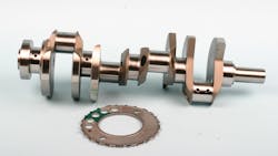
LS engines feature a toothed reluctor wheel (also often referred to as a tone wheel or tone ring), which is press-fit onto the rear of the crankshaft. This toothed wheel is used by the crankshaft position sensor for ignition timing. There are two styles of wheels. The Gen III LS1/LS6/LQ4 engines originally used the 24-tooth reluctor wheel, while the Gen IV LS2/LS7/LS3/LS9 engines featured a 58-tooth wheel. In most cases, you can identify a Gen III or Gen IV by the location of the camshaft sensor. Gen III engines featured the cam sensor mounted at the top rear of the block, while Gen IV engines feature the cam sensor mounted onto the timing cover.
Either tooth-count wheel can be installed on any LS crank, as long as you have a controller designed for the specific tooth-count. If you're starting from scratch and have a choice, it's best to go with a 58-tooth wheel and matching controller for a more accurate timing control. The reluctor wheel may require removal/replacement for a variety of reasons—the wheel may be damaged, or the crankshaft needs repair, and the wheel must be removed to perform journal resurfacing, or a new crankshaft must be installed that did not come with a reluctor wheel.
If you plan to maintain the OE original controller/engine management computer, you'll need to stick with the same version (24 or 58 tooth) of wheel that the engine's controller originally used. If you plan to use an aftermarket controller, it really doesn't matter, as long as you buy the correct timing controller that matches your wheel's number of teeth.
Basically, the OE LS cranks are identical and will install in all LS blocks (variances exist in terms of stroke, and engines that were originally fitted with dry-sump oil systems will feature a longer snout). Regardless, one of the features common to all is the need for a toothed reluctor wheel.
Whether you plan to reuse the OE crankshaft that was included in your new or used engine, or if you plan to install an aftermarket performance crankshaft, you may run into a situation where the reluctor wheel must be serviced. As noted earlier, perhaps the original tone wheel is damaged (teeth missing or bent), or maybe you have a crank with a 24-tooth wheel, and you want to switch to a 58-tooth wheel, or possibly a new crank that you bought does not include an already-installed wheel. Most aftermarket crank makers will sell their LS cranks with the wheel already installed, but you can run into a situation where the wheel is sold separately.
Here we'll explain the procedure involved in installing a reluctor wheel. It's not a simple matter of hammering the wheel onto the rear of the crank. The tone wheel must be indexed correctly to the crank. If not timed correctly relative to the crank's rod throws, the engine either won't fire at all or it will run severely out of time.
Removing/Installing the Reluctor Wheel
The reluctor wheel (also referred to as a timing wheel or tone wheel) is interference-fit onto the rear of the crankshaft, with no key or other registering device. If you've removed the tone wheel from a production crank, or if you're faced with installing a new tone wheel onto a new crankshaft, where the two components were purchased separately, it's critical to understand how the wheel is to be installed.
Removing an Original Tone Wheel
If an original tone wheel is to be removed, first place matchmarks on both the tone wheel and crank rear flange. Again...the position of the wheel is critical.
Do not attempt to remove the wheel with a puller, since you'll bend/distort the relatively thin wheel. Instead, carefully and evenly heat the wheel with a torch to roughly 200 degrees Fahrenheit. As the wheel expands as a result of heat, it can easily be pulled off by hand (obviously, you'll need to wear heavy welder's gloves). This can also be done in a cleaning oven (assuming an oven is available).
The reluctor wheel features a series of teeth that provide crankshaft position signals (via a sensor) to the ECM. The wheel interference-fits to the rear of the crank, immediately forward of the No. 5 main bearing. Typically, the wheel features about a 0.007-inch interference fit.
The Indexing Dilemma
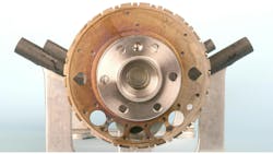
Since LS cranks feature no keyway or other index point, how do you know where to locate the wheel? Luckily, aftermarket indexing tools are available, such as the unit developed by Goodson Shop Supplies that we're featuring in this article. They offer a very handy and absolutely essential indexing and installation tool for LS reluctor wheel mounting.
The RRJ-350 Reluctor Ring Jig is comprised of a short steel tube that's equipped with two indexing pins. An external tang secures a threaded stud, with the stud tip turned down to 8 mm. This pin engages in the single 8mm indexing hole in the reluctor wheel. An internal guide pin (a threaded stud with the tip turned down to 11 mm) engages into the 11 mm blind dowel hole in the crank's flywheel flange. This jig orients the reluctor wheel precisely in the correct timing position. The two dowel studs feature jam nuts to allow depth adjustment (you simply want to make sure that the 8mm dowel passes through the wheel's 8 mm hole, and that the 11 mm dowel projects out far enough to engage the crank flange dowel hole).
Installation Procedure
For purposes of this article, I performed a sample installation. First, I lightly chamfered the entry hole of the reluctor wheel, and lightly chamfered the edge of the crank's reluctor wheel flange. Goodson's instructions advise this chamfering to ease installation.
The instructions also state that the wheel may be pressed onto the crank or heated to 450 F for a slip-on fit. Attempting to cold-press the wheel onto the crank can be tricky since maintaining a square alignment of the wheel to the crank may be difficult. Pre-heating the wheel (resulting in the center hole expanding) makes the job easier and much more controllable for a precise indexing fit.
In our example, I heated the reluctor wheel's I.D. lip with a torch and slipped the wheel onto the Goodson jig. This allowed me to smoothly slide the wheel onto the crankshaft.
You'll definitely need to install the ring by pre-heating it, instead of potentially ruining the ring by cold pressing. Pressing, if not done with a high degree of precision and care, can easily warp the reluctor wheel, rendering it useless. Do not try to force the wheel onto the crank by striking it with a hammer. That's a guaranteed way to ruin the wheel.
(Caution: The tone ring is made of two plates riveted together. If you are using a press, and if you cock it out of alignment and continue to press, the plates can begin to separate. If this happens, you can pinch the plates together with C-clamps and carefully tack-weld it back together at the rivet hole locations. Just be careful to avoid creating a warp/runout condition.)
Since this special jig indexes to both the wheel and to the crank, misalignment is avoided. If you expect to service LS engines, I highly recommend buying this jig. It takes all of the guesswork and time-consuming measuring out of the equation. Don't even try to press it on cold. Simply heat the ring, seat it onto the jig, and place the jig and wheel onto the crank. With heat and the right tool, it's easy.
Final Inspection
Once the wheel has been installed and allowed to cool, test-fit the crankshaft into the block and carefully inspect to verify that the wheel does not come into contact with the rear main cap area. With the crankshaft resting on the main saddles, slowly rotate the crankshaft to verify that the wheel features no discernible runout, and make sure that it is aligned with the crankshaft position sensor, which is located at the rear of the left side of the block.
About the Author

Mike Mavrigian
Motor Age Editor
Mike Mavrigian has written thousands of automotive technical magazine articles involving a variety of specialties, from engine building to wheel alignment, and has authored more than a dozen books that crisscross the automotive spectrum. Mike operates Birchwood Automotive, an Ohio shop that builds custom engines and performs vintage vehicle restorations. The shop also features a professional photo studio to document projects and to create images for articles and books.