Piston ring 101: Fit, assembly and tightening
We cover the basics of piston ring fit, assembly techniques and rod bolt tightening, including when to turn to the specifications from piston ring manufacturers.
Piston Ring Fit
While OE direct replacement piston rings likely will provide the correct end gap (based on original cylinder bore diameter or if the bores have been reconditioned and oversized in whatever oversize listed by the engine maker), always check to verify ring end gap. In some builds, the rings must be file-fit to obtain the recommended ring end gap. File-to-fit rings are slightly oversized, allowing the builder to obtain ideal ring gaps for the top and second rings. Refer to the piston maker’s specs for preferred gaps.
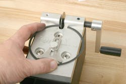
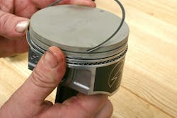
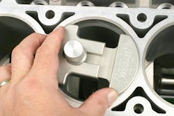
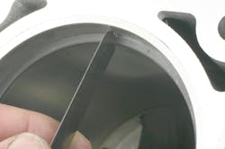
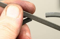
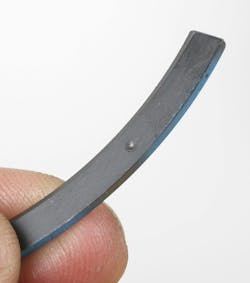
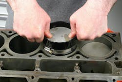
First, make sure that the cylinder is clean and dry. Carefully compress a ring by hand and insert the ring into the cylinder (Make sure that the ring is oriented properly. A dot or other mark will indicate the top side). Push the ring into the bore by about ½" to 1” below deck. It is imperative that the ring is evenly located/squared, with the distance from the top of the ring to the block deck equal along the entire circumference of the ring. This can be done by checking installed depth with a caliper, or with the use of a dedicated ring placement tool that pushes the ring squarely into the bore. Check the existing ring end gap with a feeler gauge. Remove the ring and file the ends, and re-install to check the modified gap. A ring filing tool equipped with a diamond wheel makes the task easier and more accurate. Various types of ring filing tools are available. If using a hand-operated crank tool, hold the ring flat on the tool base and rotate the abrasive wheel against one end, then flip the ring over and file the opposite end, using the same number of strokes at each end. Perform this task in small steps and re-check the gap in the bore. If you file too much, the gap will be too great and the ring must be replaced. More sophisticated ring filing tools feature electric motors and can be preset to achieve a desired gap. Regardless, after filing, each filed end must be carefully deburred using a small hand file or a built-in deburring wheel (depending on the specific tool).
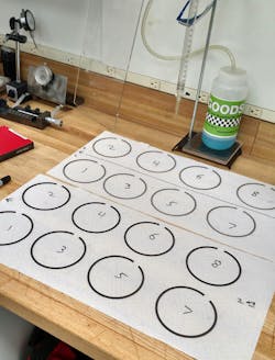
Some builders tend to check ring end gaps using one cylinder, while others dedicate each pair of rings to individual cylinders. The latter is more precise, as cylinder bore diameters might differ by a small amount. As each pair of rings is final-gapped, keep them together and label with regard to a specific cylinder. An easy method is to create a layout sheet of paper on a workbench, marking each location for cylinder number.
Check and verify ring fitment in the piston ring grooves referring to OE specs or the piston maker specs. Verify back clearance. This is the depth that the ring seats in the ring groove. With the ring fully seated to the depth of the groove wall, the ring should not protrude beyond the land. Check side clearance using a feeler gauge. With a ring seated on the groove land, measure clearance between the top of the ring to the upper shelf of the groove. This is typically in the range of 0.001-0.003”.
Piston Assembly Techniques
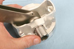
OE engines typically feature a press-pin fit of the piston wrist pin to the connecting rod. The pin is free to rotate within the piston pin bore, while the pin is interference-fit to the small end of the connecting rod. Disassembly or assembly of the connecting rod to the piston is done by heating the connecting rod small ends in a dedicated rod heater, which slightly expands the inside diameter of the rod small end. The piston is then positioned onto the rod small end and the pin is inserted. As the rod small end bore cools and contracts, the wrist pin is secured in the rod small end.
Rather than using a wrist pin that is press-fit to the small end bore of the rod, some engines use a “free floating” pin, where the pin is free to rotate in both the connecting rod small end and the piston. In these applications, the rod small end pin bore features a bronze bushing to protect the pin and promote lubrication. A notable benefit to free-floating pins is that it enhances ease of disassembly/assembly, as opposed to pins that interference-fit to the rod small end, since no press or heat is required.
In a full-floating pin design, since the pin is free to slide within the rod and piston bores, a method of retaining the pin in place is critical to prevent the pin from sliding out and hitting the cylinder walls. Pistons that accommodate a free floating pin will commonly feature a groove at each end of the pin bore to accept a pin lock.
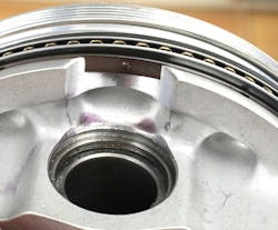
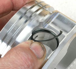
For more common pistons that require pin retention clips, depending on the piston maker’s design, this will require either a flat circlip at each end of the pin, a single round-wire circlip at each end, a single flat-wound spiral lock (often referred to as Spiro-Lock) at each end, or in some cases, two spiral locks at each end.
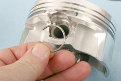
Installing a circlip that features eyelets is done with a pair of circlip pliers (compressing the clip, inserting into the groove and releasing tension). Traditional round-wire clips are compressed, slipped into the groove and released. Another style of wire clip features short angled “legs” at each end. (They are offered under the trade name “Kramm-Lox” by some suppliers.) The short “legs” engage into the piston pin bore’s clip service notch, preventing the clips from rotating.
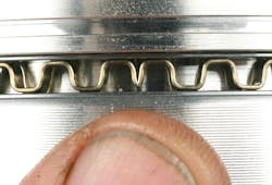
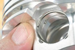
Installing spiral locks can be tricky for the first-time user but as with many procedures, once you become accustomed to the task, it’s not that hard. Slightly pull the spiral-wrapped lock apart with your fingers just enough to create a slight “coil” to expose one end. Insert the exposed end into the groove, then using a small flat blade screwdriver, push the lock into the groove by walking pressure along the clip until it fully engages and snaps into the groove. Visually confirm full seating, and tap the opposite side of the wrist pin against the clip to confirm that it’s fully seated. Special spiral clip drivers are available to ease installation, but seasoned installers develop a “knack” and tend to install spiral locks using their fingers. Spiral locks are available for all common pin sizes. Aftermarket performance piston makers include pin locks with their piston kits. (Styles of locks may vary as determined by the piston maker.)
A couple of important reminders:
- When using spiral locks, DO NOT re-use them. Install new spiral locks during each engine assembly. Also, avoid over-stretching spiral locks.
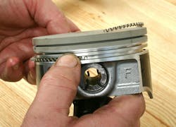
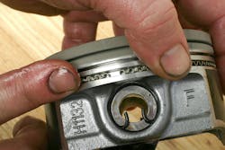
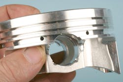
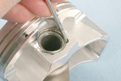
- Some applications require the use of pistons that feature a short CD (compression distance). Piston CD refers to the distance from the center of the wrist pin bore to the piston dome. Depending on the application, the CD may be reduced to the point where the wrist pin bore intersects the oil ring package groove. In this case, the piston’s oil ring groove is slightly taller, allowing the installation of an oil ring support rail on the ring groove’s land, providing a “complete” floor for the oil ring at the pin bore locations where the bore encroaches into the oil ring groove. Be aware that because the pin bore is raised, resulting in the bore intersecting the oil ring groove, the connecting rod and wrist pin (and pin locks) must be installed prior to installing the rings. If the oil ring package and support rail is installed prior to piston-to-rod connection, access to the pin bore will be obstructed.
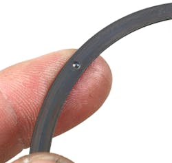
When a set of pistons requires support rails, the rails will be included along with the piston ring set. A support rail features a small male “bump” protrusion on one side of the rail. The support rail must be installed so that this “bump” faces downward, and with the bump placed directly over the pin, within the void area of the oil ring groove. This bump serves as a “stopper,” preventing the support rail from potentially rotating and preventing the rail’s gap from entering the void area.
After installing wrist pin locks, as added verification, use a brass drift and tap each end of the pin to again make sure that the locks are solidly captured in their grooves.
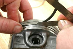
Rings must be installed carefully to avoid ring distortion. The support rail (where applicable) can be installed by hand, as well as the oil ring package (oil expansion ring, followed by lower oil ring scraper rail and upper oil ring scraper rail). Make sure that the expansion ring ends butt together and do not overlap. Once the lower oil ring rail is installed, this will hold the expansion ring together, preventing overlap. The second ring and top ring are then installed using a quality piston ring expander tool. Orient the ring end gaps per the automaker or pistonmaker recommendations. The primary goal is to prevent any of the ring end gaps from aligning to each other. Be aware that during engine operation, the rings will tend to slightly rotate in their grooves, so top and second ring end gaps should be placed well away from each other to eliminate this concern.
As far as ring end gap placement is concerned, one commonly accepted placement is that the gap of the top ring should be about 90 degrees from the gap of the second ring. End gaps of the oil ring scraper rails are commonly installed 180 degrees apart. Another approach is that the top and second ring end gaps are 180 degrees apart, and oil scraper gaps are about 90 degrees apart. If in doubt, follow the pistonmaker’s gap orientation specs.
With regard to top and second ring installation, directional rings feature a dot or the word “TOP.” Install so that the dot or TOP stamp faces upward toward the piston dome. If the top and/or the second rings feature no orientation marks, the ring is non-directional and can be installed with no regard to top/bottom. Note that if a ring is stamped “TOP,” this refers only to ring orientation and does not indicate that the ring is the top compression ring.
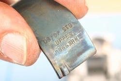
Once the piston/rod assembly is complete, install rod bearings to the connecting rod upper saddles and lower caps. Pay close attention to the rod bearings. The back of the bearings will likely be stamped “upper” or “lower.”
Apply oil or assembly lubricant to the exposed bearing surfaces. Make sure that the cylinder bore walls are clean and free of any contaminants. Lightly oil the cylinder walls. Rotate the crankshaft to position No. 1 cylinder rod journal at/near BDC (bottom dead center). This will allow optimum access to the connecting rod bolts.
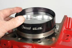
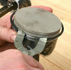
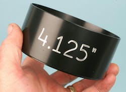
In order to allow entry of the piston into the bore, the rings must be compressed to a point of allowing the rings to enter the bore. Use a quality piston ring compressor tool to secure the rings. Several types of ring compressors are available in both diameter-adjustable and fixed-size versions. While the “barrel” style (wrapped-layer tempered sheet metal) is a common type, a billet ring compressor provides a much easier and more precise manner of ring compression/piston installation. A billet ring compressor is machined from aluminum stock and features an internal taper (wider at the top and reduced diameter approaching the bottom). The only downside to billet ring compressor tools is cost, as a specific bore diameter version is required for a given cylinder bore diameter. While a barrel style compressor may handle a specific range of bore diameters, a billet tool will be dedicated to a specific bore size. This requires purchasing individual billet compressors based on the engine block’s cylinder bore size (different engines, standard or oversize bores, etc.).
Regardless of the tool selected, apply a film of clean oil to the inside of the ring compressor to aid in the rings sliding inside the tool and to the piston rings and skirts.
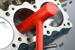
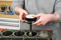
However, billet style ring compressors are also available that feature a split and a worm-drive clamp, making them adjustable within a given range of bore diameters. Once the appropriate ring compressor is selected (and adjusted for the engine’s bore size), slip the connecting rod/piston assembly through the ring compressor, to a point where the ring package is completely encased in the compressor. Orient the rod/piston relative to the crankshaft’s rod journal. (Refer to a service manual, or make sure that the chamfered side of the rod's big end faces the crank journal fillet.) Carefully insert the rod into the bore, allowing the piston skirt to enter the bore. While holding the bottom of the ring compressor firmly against the block deck — this is important — push the piston into the bore until the top ring enters the bore. This may require tapping the piston dome with a clean plastic hammer. Be gentle. If excess resistance is felt, stop and inspect. The ring package may need to be compressed a bit more — or the oil ring package may have slipped out of the bottom of the compressor.
Tap or push the piston, while monitoring and guiding the rod big end onto the crankshaft rod journal. Once the rod big end saddle/bearing is squarely seated onto the journal, install the rod’s bearing-equipped cap to the rod big end and tighten the rod bolts to recommended torque. If tapping the piston was required to engage the rings in the bore, closely inspect to make sure that the upper rod bearing shell has not moved or fallen out, before allowing rod-to-journal contact.
Once the rod bolts have been tightened, carefully rotate the crank to verify free movement of the assembly. If excess resistance or unusual noise or feeling is found, you may need to remove the assembly to inspect for ring placement.
Rod Bolt Tightening
Regardless of the application, do not reuse old rod bolts. Always install new rod bolts. When dealing with OE rods and rod bolts, follow the tightening specifications listed in the service manual. When dealing with aftermarket connecting rods/rod bolts, refer to the rod and/or boltmaker’s instructions. This will usually provide both recommended torque value as well as a maximum bolt stretch value. Most builders prefer to use the bolt stretch monitoring approach, which is more accurate in verifying bolt clamping load.
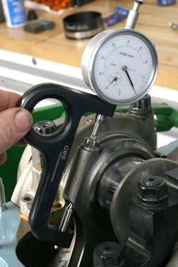
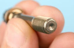
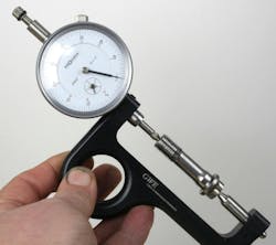
If using the stretch method, first place a rod bolt onto a dedicated rod bolt stretch gauge. Aftermarket bolts usually feature a female dimple at each end of the bolt. With a rod bolt affixed to the gauge, zero the dial gauge. This provides a reference of the static bolt length. After torquing the bolt to spec, install the same gauge to the installed bolt and monitor the amount of stretch that the bolt has experienced. The spec sheet will list the maximum allowable stretch. (Never exceed the max stretch, since this may result in bolt fatigue, exceeding its elastic property.) Using a bolt stretch gauge is time consuming, as each individual bolt must be zeroed and checked after torquing. Do not rely on the zero-setting of the first bolt to be employed for remaining bolts. Each rod bolt must be zeroed on the gauge, since the static length of all bolts may not be identical simply due to bolt manufacturing tolerances.
Repeat the rod/piston installation for all remaining bore locations, checking for crank rotation after each rod/piston installation.
About the Author

Mike Mavrigian
Motor Age Editor
Mike Mavrigian has written thousands of automotive technical magazine articles involving a variety of specialties, from engine building to wheel alignment, and has authored more than a dozen books that crisscross the automotive spectrum. Mike operates Birchwood Automotive, an Ohio shop that builds custom engines and performs vintage vehicle restorations. The shop also features a professional photo studio to document projects and to create images for articles and books.