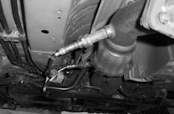
Cracking the code on catalyst efficiency
Key Highlights: Technicians Need to Know
- Modern three-way catalytic converters (TWC) reduce harmful emissions by oxidizing CO and HC and reducing NOx, relying on a well-maintained catalyst and proper engine operation.
- Onboard diagnostics utilize switch ratio and oxygen storage capacity (OSC) testing to evaluate catalyst efficiency, with each method suited to different sensor technologies and vehicle systems.
- Proper diagnosis involves understanding system-specific testing conditions, interpreting sensor data accurately, and identifying root causes like exhaust leaks or poisoning to avoid unnecessary part replacements.
- Failure to meet catalyst efficiency thresholds triggers diagnostic trouble codes (DTCs) like P0420 or P0430, along with MIL illumination, but these codes do not always indicate a faulty catalyst.
- Effective troubleshooting requires referencing manufacturer-specific service information, verifying operating conditions, and considering factors like sensor health, fueling, and exhaust integrity.
With ever-tightening emissions standards and a continuing increase in average vehicle age, accurate catalytic converter diagnostics are more important than ever. The modern three-way catalytic converter (TWC) is an oxygen storage device that plays a vital role in reducing harmful emissions such as hydrocarbons (HC), carbon monoxide (CO), and nitrogen oxides (NOx). These harmful tailpipe emissions are chemically converted into less harmful substances (nitrogen, carbon dioxide and water) by the catalytic converter, but its ability to do so depends on that catalyst being in good condition, and the engine maintaining near stoichiometric air-fuel ratio.
How Onboard Diagnostics Track Catalyst Health
To meet emissions standards, OBD-II systems need to monitor the conversion efficiency of the catalyst. Once that efficiency drops below a certain threshold, the system needs to trigger the malfunction indicator lamp, or MIL, off the detected fault, typically the P0420 or P0430 diagnostic trouble code. While specific testing methodology varies greatly by manufacturer and even vehicle model (and needs to be referenced by the technician in service information before any diagnostics begin), there are two main high level strategies employed by vehicle manufacturers to determine catalyst efficiency that technicians need to understand. These are:
- Switch Ratio: Comparing the oxygen sensor cross counts between the upstream and downstream oxygen sensor.
- Oxygen Storage Capacity (OSC): This test is based around the converter’s ability to absorb and release oxygen during changes in air-fuel ratio.
Both of these methods have their advantages and disadvantages, and vehicle manufacturers will base their chosen method of monitoring efficiency based on a variety of factors, including sensor technology. And while more vehicle manufacturers have turned largely to OSC in recent years, it’s important for the technician to understand the two monitoring strategies and their implications for diagnostics and repair.
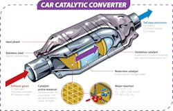
For a technician to understand how efficiency is tested, it’s vital to understand how a modern TWC functions. The TWC performs three main functions:
- Oxidize carbon monoxide (CO) into carbon dioxide (CO2)
- Oxidize unburned hydrocarbons (HC) into water (H2O) and CO2
- Reduce nitrogen oxides (NOx) into nitrogen (N2) and oxygen (O2)
To accomplish this, the catalytic converter substrate is coated with a washcoat. That washcoat is the carrier of catalyst materials and is used to evenly distribute the elements across the substrate. The washcoat consists of elements typically including platinum (Pt), palladium (Pd), and rhodium (Rh). Rhodium is used as a reduction catalyst, palladium as an oxidation catalyst, and platinum as both a reduction and an oxidation. The ability of the conversion process to efficiently take place relies on the engine operating at a stoichiometric air-fuel ratio, around 14.7:1 for gasoline engines. It is at this ratio that the right balance of oxygen occurs to support all three chemical reactions. One of the main functions of the TWC is its ability to store oxygen during lean conditions and then release that oxygen during rich conditions to keep the conversion process going, even when the engine AFR wavers slightly.
As the catalyst ages, factors like thermal degradation, contamination, or physical damage can limit the ability of the TWC to store oxygen and perform the needed chemical conversions. When this occurs, the PCM needs to be able to detect this loss, and that is where testing like switch ratio or OSC comes into play.
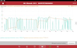
When it comes to monitoring catalyst efficiency, switch ratio is the oldest and most widely used form of catalyst efficiency monitoring. The process is simple in theory. For vehicles that use narrow-band-O2 sensor technology, the upstream sensors will sweep between approximately 100mv and 900mv in closed-loop operation as the ECM adjusts fueling strategy to keep the engine as near stoichiometric air/fuel ratio as possible. A healthy catalyst will ingest more oxygen when the air/fuel ratio is lean, and release it as the mixture fattens up, buffering those fluctuations, and leaving consistent voltage feedback from the monitoring rear O2 sensor. The ratio of fluctuation or sweep of the upstream O2 sensor(s) compared to those post converter is your switch ratio. Simply put:
Switch Ratio = (# of upstream sensor switches) / (# of downstream sensor switches)
The steadier the downstream O2 sensor voltage output, the better that TWC is performing. Adversely, a downstream sensor that is mimicking the sweeps of the upstream sensor suggests a catalyst that is no longer working efficiently.
Implementation of testing and the conditions needed to run that test will vary from manufacturer to manufacturer and even model to model. But once the predetermined parameters are met, the ECM enters it’s test mode. When testing, it will begin to monitor the cross counts from the upstream sensors (if equipped with traditional narrow band O2 sensor technology) and compare it to the cross counts from the downstream sensor. If the vehicle utilizes wide range air fuel ratio (WRAF) sensor technology, then the ECM may simulate narrowband behavior by adding and subtracting fuel during the test mode and monitoring downstream O2 sensor response.
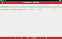
Oxygen Storage Capacity (OSC): Precision Monitoring
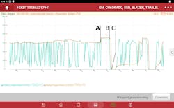
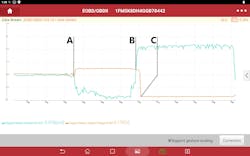
We have looked at switch ratio, now let’s take a look at oxygen storage capacity or OSC. Now this is the point many people get confused. Switch ratio testing does indeed ultimately test the converter’s ability to store and release oxygen, or its oxygen storage capacity. But the testing strategy of the ECM taking control of the mixture to measure the time-to-capacity is known as OSC testing. The OSC test is a more precise method of looking at catalyst efficiency. As stated earlier, a core function of a healthy TWC is the ability for that converter to store and release oxygen. The principle behind OSC testing is that a well-functioning TWC will delay changes at the downstream sensor during controlled air-fuel ratio changes. The ECM monitors how quickly the downstream sensor responds as it fluctuates the mixture, rich or lean. The longer the delay in shift of rear oxygen sensor voltage, in theory, the healthier the converter is because of its ability to store oxygen. A reduction in OSC of the catalyst will cause the downstream sensor to respond too quickly, which may trigger a catalyst efficiency DTC.
For a technician, the great benefit of understanding OSC testing is it can be implemented to gain a better understanding of catalyst health, even on systems that do not use it as a native testing strategy. OSC testing gives a comprehensive look into TWC health and performance because it is able to illustrate in graphical form how much oxygen, or “how big of a gulp” that converter can take. By driving the air/fuel mixture rich, forcing the TWC to deplete its stores of oxygen, and then driving the air/fuel ratio lean and allowing it to fill its lungs, that time base between when the mixture was driven lean and when the downstream O2 sensor shows a reduction in voltage is a graphical indication of that catalyst's ability to store oxygen.
OEM implementation of OSC testing as a monitor of catalyst efficiency has slowly grown in favor since the early 2010s. More and more manufacturers, such as Honda, Toyota, BMW, VAG, Hyundai/Kia, and GM, have come to implement this testing strategy. Newer vehicles with faster and more powerful controllers, and the growing implementation of wide-band air fuel ratio sensor technology, allow manufacturers to emphasize precision and early fault detection. OSC catalyst monitoring also helps keep vehicle owners honest. With a little research, one can quickly learn how to space out the rear sensor and often hide a degraded TWC in a vehicle that uses less precise methods to monitor efficiency. OSC monitoring makes attempting to cheat an emissions test much more difficult.
What Happens When a Test Fails?
With either switch ratio or OSC testing, if a test fails to meet programmed limits the ECM will do the following:
- Store a related DTC, often a P0420 (Bank 1) or a P0430 (Bank 2)
- Turn on the service engine soon light
- Log freeze frame data for the technician to use in diagnosing the problem
Often a reduction of conversion efficiency of approximately 50% compared to a new catalyst is enough to trigger the aforementioned series of events. Catalyst monitoring is a non-continuous test, so unlike fuel trim or misfire detections which run continuously, catalyst monitoring only happens under certain operating conditions. These criteria are found in service information, and vary by manufacturer, but often include parameters like:
- Engine is up to operating temperature
- Vehicle is in closed-loop operation
- Idle or stable cruise (depending on test specifications)
- No active trouble codes for things like fuel trim, O2 sensors, or misfires
- Minimum drive time since last test
If the criteria are not met, the test will not run. This is why referencing service information is vital for a technician to verify that a repair is paramount for customer satisfaction. These criteria are strict to ensure that the data gathered is accurate and not influenced by transient operating conditions.
Often the test method chosen by vehicle manufacturers depends on fueling control strategy and sensor configuration. This means a technician is far more likely to find a vehicle that uses narrowband sensors to employ switch ratio testing, and one that uses WRAF sensor technology for at least the upstream sensor to employ OSC testing. Some manufacturers, such as GM, have even started implementing a hybrid approach to catalyst efficiency monitoring. These systems will often start with a switch ratio evaluation and then confirm with OSC. This approach of dual testing can help enhance the reliability of the onboard monitoring system and reduce the likelihood of false positive results.
Avoid the Guesswork: Diagnose With Precision
When it comes to chasing down catalyst efficiency problems, this is not the time that a technician wants to start throwing parts at a vehicle in hopes that tossing that 50/50 ball yields a positive result. As I often tell my kids, it’s the painful and expensive lessons that tend to stick with you the most. Get me in a sports book in Vegas, and I’ll throw down on a juicy parlay, but I don’t want to gamble when it comes to repairs on a customer’s vehicle, especially with something as expensive as a direct fit catalytic converter assembly. There are many different things that can cause a catalyst efficiency DTC, and often the industry is quick to condemn a converter at the first sign of a P0420 or P0430 DTC without figuring out if the failure is indeed related to a degraded, poisoned or otherwise damaged catalyst. And, if that is the diagnosis, what exactly took the TWC out?
Now remember, a P0420 or P0430 does not always mean the catalyst is at fault. A vehicle has a fairly wide operating range while still being considered in fuel control. The TWC, on the other hand, has a very narrow air/fuel range it can operate within while still being effective. Because of this, a vehicle operating outside of that Lambda range of 0.995 – 1.005 can trigger a catalyst efficiency DTC. Exhaust leaks caused by things like broken manifold bolts or a broken flex pipe upstream of the TWC, or even something like a split resonator, can cause problems if close enough (generally within 15 or so inches) to the downstream sensor.
Even if you do find the converter at fault, typically, something contributed to its demise. Poisoning from coolant and heavy oil deposits can degrade the life of a TWC significantly. And though rare anymore, lead and ZDDP poisoning are still possibilities as well. Prolonged and significant over fueling can cause the converter’s ceramic substrate to start to plug, and even heat shielding that has corroded away can cause the catalyst to not maintain the correct operating temperature. Shotgunning a converter on a vehicle without performing root cause diagnostics is just inviting a comeback.
Smart Strategy = Successful Repair
Regardless of testing type, it is imperative that a technician trying to diagnose a catalyst efficiency problem research service information to determine which system they are working on, and the conditions needed to set the DTC they are chasing down to help set up their diagnostic approach. If the vehicle uses a switch ratio strategy, the technician then knows to focus on things like sensor switching activity (for narrowband O2 sensors) and O2 sensor waveform analysis (upstream versus downstream) to get a good picture of that switch ratio. For OSC, look at things like fuel trim behavior, upstream WRAF accuracy (sensor drift), and rear sensor response time.
Catalyst efficiency diagnostics demand more than a surface-level understanding of DTCs and sensor data. As we've seen, both switch ratio and oxygen storage capacity testing have distinct applications depending on sensor technology and manufacturer strategy. The key takeaway for any technician is this: don’t guess. Proper diagnosis requires an understanding of how the system is designed to work, what conditions must be met for testing to occur, and how to interpret the results accurately. Whether it's a failing sensor, an air/fuel imbalance, or a truly degraded converter, identifying the root cause is essential to avoid unnecessary repairs and costly comebacks. With the right knowledge and approach, technicians can not only fix the problem but also prevent it from happening again.
About the Author

Erik Screeden
Technical and Multimedia Content Director
Erik Screeden is the Technical and Multimedia Content Director for the Vehicle Service & Repair Group. Erik is an ASE Master Automobile Technician with L1, and L4 credentials, who has been in the industry for over 25 years in various capacities. During that time, Screeden was a technician. He started out at a Ford dealership and continued to several independent repair facilities as well as spent time in the specialty aftermarket at a GM-specific performance shop. After his time as a technician came to an end, Screeden transitioned into a role providing scan diagnostic and J2534 tool support. He was then able to parlay his experience as a technician and a support specialist and use that in several technical sales roles.
Don't miss any of Screeden's video content sign up for Autoplay.