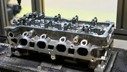
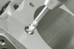
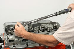
While your shop likely does not include a machine shop and you may not be involved in engine rebuilding, this article provides an overview of what is typically involved in cylinder head repair/rebuilding. The goal of this article is to provide insight regarding what may be involved if, or when, you source cylinder head work out to a local machine shop. The insight can help you (and your customer) better understand the work involved.
Cylinder head work, depending on the issue at hand, may be required due to a failed head gasket, worn or damaged valves and valve guides, cracks in the casting, etc.
Cylinder Head Deck Flatness
In cases where the engine overheats and/or leaks combustion, disassembly will often reveal a “failed” head gasket. The problem is incorrectly too often blamed on the gasket itself. When a head gasket fails or is “blown out,” the cause is far more likely to involve incorrect deck surface flatness and/or machined finish. If the engine has experienced severe operating conditions (overheated due to lack of coolant, restricted radiator hose, plugged radiator, etc.), this can easily result in warpage of an aluminum cylinder head which prevents the gasket from sealing.
Other factors can involve a poor finish of the head deck that does not allow gasket sealing, and/or improper head installation where specified bolt torque/sequence tightening was not followed. In other words, don’t be quick to place the blame on the gasket. Rather, you can view the head gasket as a “fuse” that has failed due to other factors.
Whether the head gasket has failed or not, whenever a cylinder head has been removed, always check for deck flatness before you consider re-installing the head.
A good head gasket seal requires a flat, clean gasket surface on both the cylinder head and engine block. Overheating, gasket failure, or careless handling can damage mating surfaces.
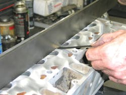
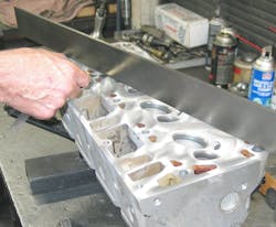
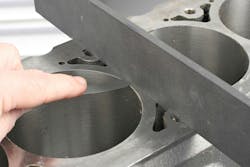
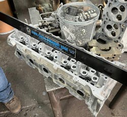
Inspect the head deck for flatness using a precision straight edge and feeler gauge. Do not rely on any “straight” piece of metal. Use only a machinist-grade precision straightedge that is purpose-made for flatness measuring.
Inspect the combustion deck and intake deck for flatness, using a precision machinist’s straightedge and feeler gauges. Measure decks from front to rear, on the intake side of the combustion chambers. Then measure front to rear at the exhaust side of the chambers. Measure diagonally (corner to opposing corners, in an X pattern). Then measure from the intake side to the exhaust side in the center and at each end of the deck.
Perform the same checks on the cylinder head’s intake deck.
As a general rule, the maximum allowable warp from front to rear or diagonal paths on a cast iron head is 0.004” or less. For aluminum heads, front-to-rear or diagonal allowable warp is 0.002” or less. Maximum allowable warp from the exhaust side to the intake side is about 0.001”. Note that any sudden or isolated warp of 0.001” or more along any 3” span is unacceptable. These tolerances are somewhat generic. Always refer to the engine maker’s specifications for allowable surface deviation.
If a flatness inspection reveals that the deck is warped beyond acceptable limits, the cylinder head may be corrected or replaced, depending on the specific application. Corrections can involve resurfacing the deck to attain true flatness, heating the head while fastened to a flatness fixture that replicates the engine block deck and allowing the head to cool, followed by a light resurfacing. If the head is to be resurfaced, always refer to the automaker’s tolerance limits in terms of how much material may be removed.
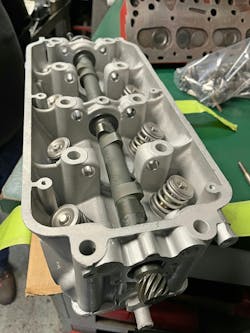
Overhead cam cylinder heads that warp along their length cause camshafts to bind in their support bearings. Upon tear down, check for warpage through camshaft bearings. When a precision machinist’s bar straightedge will not go through camshaft bores or when bore diameters are “stepped” or have different diameters, you can use the camshaft by placing it onto the saddles and trying to “rock” the camshaft in the bore, using the cam as the “straightedge.”
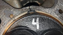
Check also for damage caused by gasket failure. For this purpose, it is a good idea to keep the original head gaskets on hand and check them for evidence of leakage. If leakage is apparent at the gasket, check the corresponding point on head and block surfaces. Depending upon the location of the leak, a “blown” head gasket sometimes permits combustion gases to burn or erode these surfaces. Be sure to find the cause to prevent repeat failures.
Corrosion damage around water circulation passages in aluminum cylinder heads is occasionally severe enough to prevent a head gasket seal. Sometimes corrosion damage extends across oil passages in the head and permits oil to enter the coolant and coolant to enter the oil. Be sure to check visually for corrosion because such problems are often the reason for removing the head. If severe, resurfacing will not correct the condition. While a weld repair might be appropriate, the best option would be to simply replace the cylinder head.
Surface Finish
Cylinder head gaskets rely on deck surface finish in order to properly seal combustion force and coolant. If resurfacing is required, chances are that your shop is not equipped with the tools needed to accomplish this, requiring you to farm such work out to a local engine machine shop. The following information is intended to make you aware of the nature of this operation.
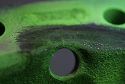
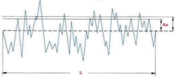
The head gasket deck surface of a cylinder head must provide a finish that is compatible with the intended type of head gasket. Surface finish requirements will vary, depending on the type of head gasket that is required (composite or multi-layer steel (MLS). Surface finish is typically rated in roughness average (RA). The RA specification represents the average across the surface of the peaks and valleys evident from surface machining.
The smaller the RA number, the finer the surface finish. While older engine designs that feature composite head gaskets may function with a surface finish in the 50-100 RA range, today’s MLS head gaskets employed with aluminum heads and/or blocks require a smoother finish to compensate for the continuous expansion and contraction of aluminum as engine temperatures increase and decrease. The majority of today’s aluminum heads require an RA in the 30 range, but some OE specs for certain engines can require even finer finishes in the 20-30 RA range — or even finer. If the finish is not smooth enough, excess “bite” can occur at the gasket, preventing the head from moving during thermal expansion and contraction, which can easily lead to gasket damage and subsequent coolant, oil and/or combustion leaks.
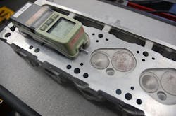
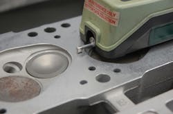
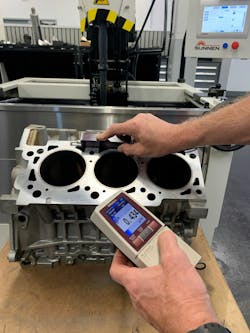
In order to actually measure the RA of a surface, a special tool called a profilometer may be used. This tool features a moving stylus that runs across the surface and displays the RA in a digital screen. If a profilometer is not at hand, resurfacing milling machine manufacturers provide a chart of recommended feed rates and cutting speeds in order to achieve a specific RA finish. Again, this is something that the typical repair shop will be unable to do, but the purpose here is to provide an insight regarding what is involved.
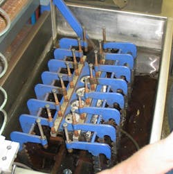
While cylinder head resurfacing may be accomplished with either a wet grinding station or a dry milling machine, milling is preferred, since it’s faster, allows greater cutting depths per pass and does a superior job of achieving a fine surface finish. Wet grinding is usually limited to removing 0.005-0.001” per pass. Milling (with cutters lightly lubricated to prevent aluminum from building up on the cutters) allows one deep-cut pass to eliminate warpage, followed by one light dressing pass to achieve the desired RA. However, in order to achieve the desired fine RA finish for aluminum heads and MLS gaskets, light cuts per pass and lower feed rates are recommended. Again, the resurfacing machine maker will provide recommendations for traverse feed rate and cutting speeds. Cutter inserts are typically carbide or cubic boron nitride (CBN) for cast iron heads and carbide or polycrystalline diamond (PCD) for aluminum heads. When milling aluminum heads for a fine RA finish, the rule of thumb is to increase the cutter rpm and slow down the feed rate (for example, a traverse feed rate of about 2-3” per minute).
Naturally, removing material from the cylinder head deck moves the combustion chambers closer to the pistons, with related potential issues of pushrod length, valvetrain geometry, increased compression ratio, potential valve-to-piston clearance, potential misalignment of intake manifold ports, etc.
In general terms, resurfacing should be limited to no more than 0.010” of material removal. Again, always refer to the engine manufacturer’s recommendations before you consider resurfacing. Your local machine shop should be able to make the determination of whether to resurface or to replace the head.
Keep in mind that these issues may be corrected by simply using a thicker head gasket. Various-thickness head gaskets are readily available for most popular engines, especially when dealing with MLS head gaskets, where thickness can be manipulated by the thickness or number of stainless steel support layers. Makers such as Fel-Pro, Mahle-Victor and Cometic offer a variety of head gasket thicknesses for various engine applications.
With that said, the reality is that, for repair shops that are not engine reconditioning specialists, quite often the practical solution to correct for deck warpage and/or surface finish may be to simply replace the cylinder head with a new head, which obviously saves a great deal of time and allows getting the vehicle back into the customer’s hands in a shorter timeframe.
Determining Valve Guide Wear
Check valve guide wear or “bell-mouthing” that occurs at each end of valve guides. The wear is greatest at the port end of the valve guide because of the extreme heat and deposits carried into the valve guide on the valve stem. Measure valve guide wear by taking measurements of the valve guide in the least worn part of the guide — the middle — and at the port end where it is most worn. The difference between the two measurements is the amount of wear.
Valve guide wear is extremely important in deciding upon what procedures to use in restoring specified valve stem-to-guide clearance. Many manufacturers do not give specifications for valve guide diameter but instead give the valve stem diameter and the range of valve stem-to-guide clearance. The valve stem must first be measured and compared to specifications.
Valve guides can be checked more quickly using go-no-go methods. First adjust a micrometer to the valve stem diameter plus maximum valve stem-to-guide clearance. Next, set a telescoping gauge to the micrometer setting and then check if it enters the valve guide. If it enters, the guide is worn beyond limits. If it does not enter, clearance is within service limits.
Be aware that oversized valve stems are used to correct for wear in integral valve guides. Should this be the case, compare valve guide diameters to measured valve stem diameters to find the clearance or wear.
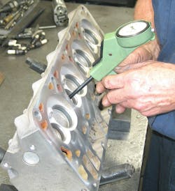
Measure valve stem diameter using a micrometer and record the dimensions. Use a small bore gauge to measure valve guide inside diameter and record this. Compare the readings to determine existing valve-to-guide clearance and compare this to specification.
Checking Valves
It saves time to inspect valves before regrinding the faces. Set aside valves that show damage wear beyond service limits before cleaning if possible. Do not waste time refacing such valves.
Check the thickness of valve margins first. The thickness of the margin after grinding should be no less than 1/32" (.8mm) or half of the new thickness, whichever is greater. For passenger car engines, replace valves thinner than 1/32" or they will burn. For heavy-duty applications, replace valves that are thinner than one-half of new thickness. If in doubt, check the manufacturer’s recommendations regarding minimum specifications.
Measure valve stem wear with a micrometer. Service limits allow .001 to .0015" (.03-.04mm) taper or variation in the diameter of the valve stem along its length. Keep in mind that manufacturers do specify stem diameters and that valve stems worn under minimum specified diameters will not assemble within specified limits for clearance. Be sure to check specifications because some valve stems use a taper to compensate for uneven heat expansion along the stem.
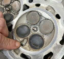
Also inspect the heads of valves visually for damage such as warpage, burning, or cupping, or pit marks. Keep in mind that valve burning follows a sequence beginning with unequal cooling, warpage, and then burning. Cupping occurs when the valve overheats all around the head. Look also for a necking down of the valve stem beneath the head that suggests stretching. Replace valves with such defects as they indicate exposure to extreme engine heat and the kinds of damage that cause failure. For some engines, it is safer to replace exhaust valves, not regrind them, during valve service because of the frequency of heat damage and the potential for failure. Measure used valve stems at three locations, at center of stem length, above center and below center. Any variations indicate wear.
Check for grooves worn in the faces of valve stems caused by defective “valve rotators.” A visible single wear mark/wear line indicates that the valve has not been rotating. Valve rotators cause valves to rotate each time they open and prevent warpage by maintaining uniform heat distribution around the valve head. Although rotators sometimes sit under valve springs, they most often serve as valve spring retainers. While rotators were common for many years in heavy-duty truck engines, they are now common in passenger car engines, especially for exhaust valves. Replace rotators when grooves appear in the faces of the valve stems showing non-rotation.
Check keeper grooves for wear or damage. Worn keeper grooves prevent the keepers from properly locking to the valve stem. Sometimes the grooves wear so evenly that they appear as if they were made that way. If in doubt, compare worn parts to replacement parts and wear will be apparent.
The importance of maintaining correct guide clearance and carefully checking valves cannot be over emphasized. Considerable heat transfers through valves, valve seats, and guides into the cooling system, therefore, valve seats and guides not kept within service limits cause valves to overheat and fail.
Flaw Detection
Inspecting a cylinder head for cracks can be accomplished by pressure testing, or with a dye penetrant system.
Pressure testing requires blocking off water passages and pressurizing water jackets to three times cooling system pressure. To simplify testing, several manufacturers supply test plates to fit specific engine applications. These plates, with a rubber gasket, are clamped/bolted on to the face of the cylinder head using threaded rods, flat washers, and nuts. When submerged in the pressure tester tank, pressurized air is injected, with any leaks (cracks, pinholes/pits, etc.) evident by escaping air bubbles.
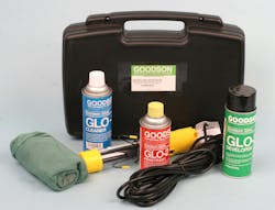
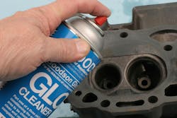
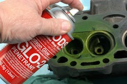
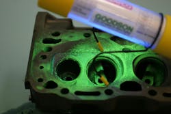
If a pressure tester is not available, a dye penetrant may be used, which is applicable to both iron or aluminum heads. The cylinder head casting must first be cleaned of excess oil/surface contaminants. Dye checking involves spraying a cleaner to the suspected area, followed by spraying a penetrating dye, and then spraying a special developer. Using a black lint, the area is then inspected. Any cracks will be visible by a color (green, red, etc.). If a crack is found, depending on the location and severity, it may be possible to repair the crack. In most cases, it may be more practical to replace the head.
Head Installation Tips
Installing a cylinder head requires attention to detail in order to achieve a proper gasket seal and to avoid comebacks.
The block and head decks must be clean, flat, and provide the required surface finish.
Always check all threaded female holes in the block deck for cleanliness and thread condition. Dirty or deformed threads will not allow proper torque value to be achieved. Never use a conventional cutting tap — use only a dedicated “chaser” tap. This type of tap is not designed to cut or weaken existing threads. Rather, a chaser tap cleans and re-forms the threads.
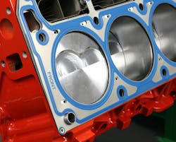
Install the required locating dowels to the block deck. This accurately registers the gasket and head in position. Place the head gasket onto the block deck, paying close attention to gasket orientation to avoid blocking off critical oil or water passages. Some head gaskets are marked “front” to aid in positioning. Take your time when placing the gasket — check and re-check for orientation.
Unless specified by the automaker, never apply any sealant/glue to the gasket. While old-school copper gaskets may require a sealant, today’s composite or MLS gaskets are designed to be installed dry.
Carefully place the head onto the block and gasket, registering to the locating dowels. Always use new head bolts, especially if the engine requires the use of torque-to-yield bolts. Pay attention to bolt length, as lengths may differ among the set. Refer to the service manual for bolt locations where lengths vary.
Never install head bolts dry. Follow the manufacturer recommendations, which may include the application of oil, a specific thread lubricant, or a thread sealant in those cases where a bolt hole may be open to water or oil. Lubricant may also be required under the bolt head. Again, follow the service manual specs.
Hand install all bolts and washers. (Sashers are always required for aluminum heads.) Tighten the bolts in stages, following specified tightening pattern and torque specs. Some engines (when using OEM bolts) require a torque-plus-angle procedure. Never use an impact wrench when installing head bolts!
Cylinder head inspection, repair and installation includes much more that we have space to discuss in this article (valve refacing, valve spring testing, overhead cam lifter buckets, etc.). Hopefully, this provides you with a rudimentary overview.
About the Author
Mike Mavrigian
Motor Age Editor
Mike Mavrigian has written thousands of automotive technical magazine articles involving a variety of specialties, from engine building to wheel alignment, and has authored more than a dozen books that crisscross the automotive spectrum. Mike operates Birchwood Automotive, an Ohio shop that builds custom engines and performs vintage vehicle restorations. The shop also features a professional photo studio to document projects and to create images for articles and books.
