Welcome back to another edition of “The data doesn’t lie,” a regular feature in which I pose a puzzling case study, followed by the answers to the previous issue’s puzzle.
Since the launch of my first class “Pressure waveform acquisition and analysis from the inside out,” its popularity has gained a lot of traction. One of my students, Scott Jett (of Express Oil) in Ooltewah, Tenn., offered a documented case study that tells the story well.
Scott was addressing a 2015 GMC Yukon with a misfire under all operating conditions. The engine seemed to crank over well and didn’t exhibit any audible clues to a loss of compression. From class Scott recalled the approach of working smarter and not harder. He used easy-to-perform tests to guide him toward much more pinpointed tests he should invest in.
Scott began with a simple relative compression test. The test didn’t support a loss of cylinder charge capable of causing a misfire. With that, Scott moved on to analyze graphed data PIDs from the scan tool. The results of the data PID analysis virtually eliminated a misfire due to improper air/fuel ratio or lack of adequate and properly timed spark ignition.
Testing Limitation Awareness
An accurate and efficient diagnosis is based around logical decisions. Understanding what a test result cannot tell you is just as important as understanding what it can. The relative compression test demonstrates the cylinder's ability to harness and squeeze the contents within and compares that ability to those of the other cylinders of the engine. It cannot demonstrate the cylinder's ability to breathe (pump air/ inhale, and exhale).
With that, Scott performed the in-cylinder pressure transducer testing. This testing demonstrates a cylinder’s ability to pump, harness and squeeze its contents. Performing this test under different operating conditions will flush different faults to the surface and provide a diagnostic path to follow.
Pressure Waveform Acquisition and Analysis
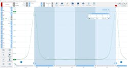
The cranking in-cylinder waveform indicates the cylinder seals just fine. It also shows how the piston moves air in and out of the combustion chamber, via the intake and exhaust valve. No problem appears to be present in this cranking capture (Figure 1).
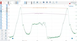
However, this running capture shows something very wrong with this cylinder (Figure 2). The low compression is apparent by the short amplitude of the compression towers. The fact that the towers appear to be leaning to the right indicates the piston ascending builds compression at a rate that is significantly slower than the loss of pressure, as piston descends. This is a classic characteristic of a severe loss of cylinder charge — a leak. The one thing this capture doesn’t tell us is the location of the leak point within the cylinder.
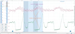
A second lab scope trace was added to the capture. This was derived from a delta pressure transducer (one that reacts swiftly to changes in pressure). The approach is to analyze the capture where the traces correlate with one another (Figure 3). What is apparent, and indicative of the fault, is the change in the delta pressure sensor trace that correlates with the opening of the suspect cylinder’s intake valve (derived from the in-cylinder trace).
The Data Doesn’t Lie
With all the information in front of us, and the desired information not yet obtained, we are faced with deciding how to proceed. Here are some bullet points of what we know to be factual, and I will ask all of you, diligent readers, for your input on what they mean to you, collectively:
- Misfire under all operating conditions.
- Data PIDs point toward engine mechanical fault.
- In-cylinder testing shows no loss cranking, but significant loss with engine running.
- Change in intake pressure correlates with suspect cylinder’s intake valve duration.
Given this information, what would you do next?
- Replace the piston/rings/recondition block.
- Replace the intake valve spring.
- Machine the cylinder head gasket surface.
- Replace the exhaust valve spring.
About the Author
Brandon Steckler
Technical Editor | Motor Age
Brandon began his career in Northampton County Community College in Bethlehem, Pennsylvania, where he was a student of GM’s Automotive Service Educational program. In 2001, he graduated top of his class and earned the GM Leadership award for his efforts. He later began working as a technician at a Saturn dealership in Reading, Pennsylvania, where he quickly attained Master Technician status. He later transitioned to working with Hondas, where he aggressively worked to attain another Master Technician status.
Always having a passion for a full understanding of system/component functionality, he rapidly earned a reputation for deciphering strange failures at an efficient pace and became known as an information specialist among the staff and peers at the dealership. In search of new challenges, he transitioned away from the dealership and to the independent world, where he specialized in diagnostics and driveability.
Today, he is an instructor with both Carquest Technical Institute and Worldpac Training Institute. Along with beta testing for Automotive Test Solutions, he develops curriculum/submits case studies for educational purposes. Through Steckler Automotive Technical Services, LLC., Brandon also provides telephone and live technical support, as well as private training, for technicians all across the world.
Brandon holds ASE certifications A1-A9 as well as C1 (Service Consultant). He is certified as an Advanced Level Specialist in L1 (Advanced Engine Performance), L2 (Advanced Diesel Engine Performance), L3 (Hybrid/EV Specialist), L4 (ADAS) and xEV-Level 2 (Technician electrical safety).
He contributes weekly to Facebook automotive chat groups, has authored several books and classes, and truly enjoys traveling across the globe to help other technicians attain a level of understanding that will serve them well throughout their careers.


