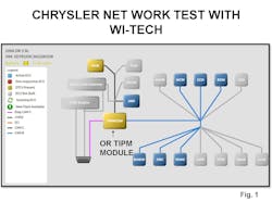
It is becoming increasingly important on modern day systems in our initial diagnostics to conduct a full system network test. In doing so we are checking to see if a module is on line and communicating and whether the module has detected a DTC. Fig. 1 from a late model Chrysler system using the OE Wi-Tech scan tool indicates that the modules color coded in blue have reported no DTCs. The modules in yellow are communicating and have reported a DTC, while the modules that are color coded in gray indicate these modules are an option and are not included in the network on this vehicle.
The modules that are yellow include the TIPM module and the PCM. The framework in this article will revolve around the late model Chrysler systems that use this TIPM module. TIPM stands for Total Integrated Power Module. This module is sometimes referred to as the Central Gateway Module. This module is known as the bus master module whereas all data from every module on the high speed bus circuit goes through the TIPM module and then the data is sent to pin 6 and pin 14 on the DLC. This module is responsible for powering up pretty much all components. You may have a no start with no fuel pressure and the issue may be a bad TIPM module. You could have a turn signal problem and the problem could be the TIPM module. Aftermarket scan tool network tests are shown in Fig. 2 . Notice the list of the modules that have reported and indicate no DTCs.
The TIPM module has a poor track record for various failures. There have been cases on a no-start where we wiggled the harness connectors and found that the vehicle started. Many Chrysler TIPM modules have a solid state integrated fuel pump relay. This is known as a pattern failure and Chrysler has issued a TSB to install a common external ISO type relay to correct this issue. The TIPM is also responsible for powering up the headlights meaning you could have a head light out and the problem could be in the TIPM module.
The standard procedure in the event whereas no communication problem exists is to disconnect the battery and ohm out pins 6 and 14. Normally with two 120 ohm resistors in parallel in the high speed network the ohmmeter should read 60 ohms. In addition the ohmmeter reading between pin 6 and pin 14 to pin 16 which is B+ should indicate an open. Continuing with our ohmmeter test between pin 6 and pin 14 to ground should also indicate an open. These tests cannot be done on the Chrysler systems simply because of the TIPM module being the bus master. These ohmmeter tests must be done at the TIPM module on the class C high speed terminals. Refer to Fig. 3.
In addition there will not be any activity on the high speed network until a scan tool is connected and a request from the scan tool is sent to the TIPM module. This is where we select a specific module where the DTC exists or where we think the problem may be. In cases where the ohmmeter test proved OK we would need to look at the signal at pins 6 and 14 with a DSO. Without a scan tool request the voltage signal at pins 6 and pins 14 will be at rest at 2.5 volts. See Fig.5.
With a scan tool connected and a request made to the TIPM module, pin 6 voltages will toggle between 2.5 and 3.5 volts while the voltages at pin 14 will toggle between 2.5 and 1.5 volts.
See Figs.6 and 7.
This is a standard uniform protocol on all CAN compliant systems. A 16 pin breakout box is a needed tool. See Fig. 8. Some later Chrysler systems incorporate a gateway module which serves as a bus master. If these signals are corrupted it will be necessary to disconnect one module at a time to see if the signal returns to normal.
Now let’s look at some specific data from the TIPM module. In Fig. 9 notice that the TIPM is responsible for powering up the A/C compressor. In the event of no A/C operation, this data is what we need. If an A/C request is made by the driver, the TIPM module will send out battery voltage to the A/C compressor. In addition notice the A/C pressure sensor indicating 1.9 volts. This assures us that a sufficient A/C charge is present. Notice also the 5 volt reference needed to power up the A/C pressure sensor is included.
Continuing on with data from the TIPM module, let’s look at Fig. 11. Notice some inputs such as battery voltage. This was captured during KOEO conditions. Battery voltages seen here below 9.2 volts will cause the TIPM module to shut down. Notice in addition the TIPM module has sent system voltage to the blower motor. The brake switch status is also shown. The TIPM module can display a charging failure. The PCM is still in charge of controlling the alternator field current. In the event of a charging system failure the PCM will bus the failure to the TIPM module.
Let's look at more data from the TIPM module. In Fig. 10 we see that the TIPM module sees the request for the wipers and sends out battery voltage to the wiper motor. I recently had a technician in my class who had a customer with a complaint that the wipers would not work. He replaced the wiper motor to no improvement. He didn’t realize the data from the TIPM was what he needed. The problem turned out to be a bad TIPM module. Looking at more data from the TIPM module in Fig. 11 we see that the TIPM module is responsible for powering up the blower motor. In addition notice the brake switch status is shown as well as the engine temperature.
Continuing on with more TIPM data in Fig. 12, notice that TIPM is responsible for powering up the headlights. Notice the left low beam is listed as well as the duty cycle to the left high beam. The TIPM will pulse the high beams at a 40 hertz frequency with a duty cycle command. We actually had a customer come in with the left headlight out. The car owner replaced his own headlight with no improvement. The problem turned out to be a bad TIPM module.
Fig. 13 tells us that the fuel level sending units report fuel level to the TIPM module. Notice that there are two sending units on this vehicle that has a saddle type gas tank.
Fig. 14 shows the ignition switch status and indicates that the key transponder has been properly read.
Notice the data in Fig. 15 that indicates that the TIPM module is responsible for powering up the two cooling fans. Be careful here and be mindful that some cooling fan drivers are of the solid state type and a shorted cooling fan can and will blow these solid state drivers.
In addition notice the PRNDL status is indicated. Fig. 16 shows us the status of the right front turn signal request as well as the right low beam and the right high beam duty cycle.
Fig. 17 shows us that the TIPM ground side controls the radiator fan relay and is responsible for powering up the rear wipers.
Fig. 18 is a partial list of the KOEO test functions available via the scan tool on these Chrysler systems. Fig. 19 is where we select data from an individual module.
We have to give the folks at Chrysler a lot of credit here in making diagnostic decisions by being aware of all of the data available from the TIPM module.
Thanks for your commitment to this very resilient industry. The industry is better because of your commitment.
About the Author