Spark Ignition and O2 Sensor Diagnostics
As the saying goes, “a picture is worth a thousand words.” In this article, our picture will focus on analyzing primary and secondary ignition waveforms, as well as oxygen sensor diagnostics.
I have always stated that a primary or secondary waveform is the heartbeat of the internal combustion engine. If you have ever had a medical EKG and looked at the paper printout, you can easily see the semblance between the EKG and secondary or primary ignition waveforms.
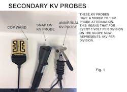
Accessing the primary or secondary side of the ignition systems on some late model vehicles is a real challenge. In addition, many COP-type coils are so heavily potted that the magnetic field is too weak when attempting to obtain a secondary ignition waveform, which presents a real challenge when using a secondary KV probe. See Fig. 1. Secondary leads are available from AESwave.com to connect to the coil and spark plug and then clamp around the plug wire with a KV probe. Remember the secondary firing events are negative polarity so you must use your invert function. Nevertheless, access to the primary or secondary side of the coils is available on most late model vehicles. Spark testers are usually our first choice in the event of a single cylinder misfire. All COP coils have the ability to fire a 30 KV event. There are various spark testers available, but we must understand the KV demand of these spark testers to stress a coil. See Fig. 2. Spark testers are used to stress a coil. A consistent blue spark will tell us that the coil is performing properly when using the right spark tester.
When possible, we prefer to monitor a primary or a secondary waveform using our DSO and focus initially on the spark duration period during a park no load condition followed by a light power brake condition. We will primarily focus on the spark line because it is our electronic window inside the combustion chamber. The spark line angle and duration period will literally mirror each other so it will not matter which side of the coil you access. See Fig. 3. Access to the primary side of the coil is usually very easy on the Ford and Chrysler systems.
Let’s look at a vehicle that suffered from a light load misfire. The engine is a distributor-equipped engine. We used the universal KV probe on the coil tower. See Fig. 4. Notice the short spark duration period in Fig. 5 during a park idle no-load condition. The engine had the spark plugs recently replaced with no improvement. Notice the major increase in the spark duration period after the distributor cap and rotor and plug wires were replaced in Fig. 6. The light load misfire was gone.
Ford is so sensitive to light load lean density misfires that the PCM will multi fire the coils below 1,000 rpm. See Fig. 7.
Lean density misfires are seen easily on the secondary or primary side of the coil. The Snap-on units and the Master Tech 5200 scopes allow us to raster the secondary side as seen in Fig. 8. Notice the short spark duration period from the No. 6 cylinder captured during a light power brake condition. Rich air fuel conditions can easily foul spark plugs as seen in Fig.9. Notice the high KV point and the sloping down spark lines from No. 2 cylinder.
I had a tech call on a 5.3L Chevy Silverado with a misfire on No. 1 cylinder. The shop had replaced the spark plugs and the coil for the No. 1 cylinder. The COP wand was laid next to the No. 1 plug wire on this coil-near-plug system. What is the waveform telling us in Fig. 10? Notice the very low firing KV value of 4 KV and a very long spark duration period of over 3 milliseconds. The compression on the cylinder measured 20 psi. Notice in Fig. 11 the secondary waveform after the exhaust valve was replaced showing a good firing line voltage of 10 KV and a good spark duration period of slightly over 2 milliseconds.
Many times on my tech calls to other shops, the problem turns out to be something the technician overlooked. This 4.0L Ford engine exhibited a light load misfire on cylinder No. 3. All of the secondary components were replaced by the truck owner. The technician working on the truck enlisted in a tech line service and was told the valve springs were known to cause this problem. The technician replaced both valve springs on cylinder No. 3 to no avail. I simply went to the shop and scoped out cylinder No. 3. See Fig. 12 from an open in the spark plug resistor.
A Toyota came in with misfire under load complaint. The spark plugs were replaced by the truck owner. This is a DIS type ignition system with an external ignitor. We simply probed the primary negative terminal at the ignitor for coil pack ¼. First notice the decay on the ¼ coil in Fig. 13 stating that multi ground electrode spark plugs must be used. The primary ignition waveform is shown in Fig. 14. Notice the very short spark duration period from the primary side of the coil. We removed a spark plug and found aftermarket single electrode spark plugs. We replaced all the spark plugs with OE multi-ground electrodes. Now in Fig. 15 notice the good spark duration period with the misfire now gone.
On the Chrysler systems the coils are controlled by the primary drivers inside the PCM. Chrysler now gives us scan data indicating the time of the collapsing magnetic field which is essentially the spark duration period. This is the artificial intelligence from the automotive industry and should be used for comparison purposes only. Fig. 16 indicates a shorter than normal value of the No. 1 cylinder compared to the other cylinders. The vehicle simply needed new OE spark plugs.
Since the primary drivers are inside the PCM on the Ford systems, Ford is doing what Chrysler is doing in that it times the collapsing magnetic field as shown by scan data in Fig. 17. This was captured above 1,000 rpm where the PCM reverts to a single firing event. Again, this data should be used for comparison purposes only. In Fig. 18 a capture was done below 1,000 rpm indicating a cylinder with a long spark line. This could be caused by a rich fuel condition or a low compression issue. Fig. 19 is from a Ford system indicating a short spark duration. This could be caused by a lean cylinder especially if this data shows up during a light power brake condition. In Fig. 20 Ford is timing the crank angle values after a firing event from the CKP sensor. Notice the acceleration PID for cylinder No. 4.
One of my favorite tests is to do a WOT clear flood cranking mode and to monitor the KV value and the spark line characteristics. Good compression values will create elevated KV demand. Notice in Fig. 21 the KV demand exceeded 14 KV with a spark duration period of over 2 milliseconds. This verifies good compression and stresses the coil for good performance. In Fig. 22 we conducted the WOT cranking test on a 4-cylinder using the bar graph function of the scope. Notice the 27 KV to 30 KV demand indicating good compression and stressing the coils.
There are three types of oxygen sensors currently used by the manufacturers. The standard and most popular Zirconia oxygen sensor, the Wide Range oxygen sensor and the Titanium oxygen sensor. Fig. 23 illustrates the zero to 1 volt scale for the Zirconia sensor. You can see that 450 megavolts represents 14.7-to-1 air fuel ratio. The issue we have with these sensors is that they cannot see full enrichment or full enleanment. However, all downstream oxygen sensors are Zirconia-type sensors. Fig. 24 shows the relatively new wide range oxygen sensor. These sensors can see a full rich condition and a full lean condition.
You can see that 2,200 megavolt represents a 14.7 air fuel ratio. Ford systems are also using the new wide range air fuel ratio sensor. In Fig. 25 notice that the value is displayed in a milliamps value. When the milliamps value goes positive, a lean condition exists. When the milliamps value goes negative, the exhaust condition is rich. Fig. 26 shows the heater control from a Hyundai system. You can see that the heater circuit is supplied voltage from a relay and the PCM ground side controls the current flow. These heating elements are of the 40-watt standard. This allows quicker heat up and faster operation into closed loop condition. Looking at the voltage supply and the current flow value in Fig. 27 you can see that the amperage peaked at about 1.6 amps.
The industry is better because of your commitment.
About the Author