Keeping the internal combustion engine as close to the stoichiometric ratio as possible will result in optimum catalytic converter efficiency and fuel economy. The stoichiometric ratio simply means that all the air (14.7 parts) and fuel (1 part) going into the cylinders are being converted to water and carbon dioxide exiting the exhaust. This is the perfect combustion reaction, but this desired stoichiometric operation can’t happen without fuel control.
Engine fuel control or closed loop operation is conducted by using the real time data from the oxygen or Air Fuel Ratio (AFR) sensors (and many other engine sensors) that are measuring and reporting the oxygen level that is in the engine’s exhaust gas stream. When the Powertrain Control Module (PCM) gets this exhaust oxygen level data it will adjust the amount of fuel that the engine gets, always trying to keep as close to stoichiometric as it can.
The oxygen or AFR sensor isn’t really measuring the amount of oxygen in the exhaust gases. Rather, it is measuring the difference in the amount of oxygen in the exhaust versus the amount of oxygen in the air. (We will cover this better in a bit.)
Today’s oxygen sensors or the more common AFR ratio sensors are very efficient at measuring the amount of oxygen that is in the exhaust system and providing that information to the PCM that will make the needed adjustments to the amount of fuel that it is supplying to the engine. The technology has progressed to the point that the PCM can adjust the amount of fuel that each individual cylinder is getting (Individual Cylinder Fuel Control or ICFC). If one specific cylinder has been over or under fueled, the PCM will adjust the fueling, specifically compensating for that cylinder’s fueling needs.
The main difference between an AFR sensor (often called “the wideband sensor”) and the standard oxygen sensor (often called the “narrowband sensor”) is their operational sensing range. The AFR sensor can detect a much wider and leaner range of fuel mixtures. This larger sensing range enables better fuel control over a much wider engine operating condition.
Today’s AFR sensors are capable of reporting exhaust oxygen levels (a reflection of fuel mixture) under wide open throttle or very lean burning cruise operations, something that the earlier oxygen sensor was simply not capable of doing. Keeping the fuel control as close to stoichiometric as possible allows the catalytic converter to function at maximum efficiency, improving emissions, but this stoichiometric operation also ensures the best fuel economy as well. This wider spectrum of operation is why the AFR is now the preferred exhaust sensing device. But the standard oxygen sensor is still being used to check the oxygen storage capabilities of the catalytic convertor, and in many cases these “catalytic convertor monitor” oxygen sensors are being used to fine-tune the engine’s fuel mixture to maximize engine and catalytic convertor efficiency.
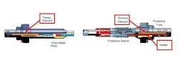
The simplest oxygen sensor uses a porous ceramic sensing element with a platinum covered area for oxygen detection. The Titania sensor uses a porous ceramic sensing element made of titanium dioxide and platinum-coated detection areas. The Zirconia sensor uses a Nernst cell for oxygen detection. The Nernst cell is made up of a porous zirconium oxide ceramic sensing element and platinum-coated detection areas. The common wideband AFR sensor is going to use a combination of devices; a Nernst cell and a pump cell to detect and report oxygen levels in the exhaust.
The common part of these oxygen and AFR measuring devices is the fact that they are all using a process called diffusion. This diffusion takes place across the porous, precious metal coated ceramic sensing element and allows the comparison of the oxygen content of the outside air to oxygen content of the exhaust gases.
The porous sensing element that allows the diffusion must be kept free of debris and contamination for it to accurately detect the difference in oxygen levels. If the surface of the sensing element becomes coated or contaminated with a foreign substance it will become poisoned or suffocated and will no longer allow proper oxygen diffusion. As the sensing element chokes, the sensor’s output will become slower, lazy, and less accurate and over time eventually will fail completely. But a poisoned sensor isn’t the only frequent cause of death for an oxygen or AFR sensor. The internal heater can also fail. For proper oxygen and AFR operation the sensing element must be kept hot. The sensing element is heated by an internal electrical heater to a functional temperature of 600 F (316 C) to 665 F (350 C) for sensor operation.
The PCM is constantly watching the oxygen and AFR sensor output for fuel control information. The PCM will be looking at the data that it is receiving from the oxygen and AFR sensors and comparing it to preprogrammed data to ensure the oxygen and AFR sensors are supplying accurate data. The PCM knows how much air the engine is consuming, how much fuel it has added and what range of values it expects to see from the oxygen, or AFR mounted in the exhaust. The PCM also knows what the resistance value and current flow of the oxygen and AFR heater circuits should be, so it will be keeping an eye on those values too. If any of these values or parameters go too far out of range for too long, a Diagnostic Trouble Code (DTC) is going to be set and turn on the Service Engine Soon (SES) light on the dash alerting the driver of the issue.
There are many oxygen and AFR OBDII codes and manufacturer-specific codes for slow, insufficient, heater circuit or stuck rich or stuck lean codes. A P0134 - Oxygen Circuit No Activity Detected (Bank 1, Sensor 1) or P0133 - Oxygen Circuit Slow Response (Bank 1, Sensor 1) are examples of OBDII codes that could easily be caused by oxygen or AFR sensor contamination.
The 2016 Dodge Grand Caravan 3.6 V6 commonly displays manufacturer specific P219A Air Fuel Ratio Cylinder Imbalance Bank 1. This code is being set because the AFR sensor can detect and look at the individual exhaust pulses from each cylinder on Bank 1 using ICFC. It has detected a fuel control imbalance of 15% between cylinders. This P219A code can be associated with bad or dirty fuel injectors or a bad camshaft, two issues that are common on the 3.6 V6 Caravan. The 2019 5.3 and 6.2 V8 GMC pickups may display a P015B: Oxygen Sensor Delayed Response - Lean to Rich (Bank 1 Sensor 1). This DTC can be set on some trucks because of water intrusion into the oxygen sensor harness connector, smothering the fresh air side of the AFR sensor element.
Oxygen and AFR heater failures are common on higher mileage vehicles but so is the poisoning or contamination of oxygen and AFR sensors. Frequent causes of oxygen and AFR contamination come from the soot of excessively rich mixtures or heavy engine oil consumption. Silicates in the engine’s coolant system can leak internally into the engine and reach the exhaust and the oxygen or AFR sensors. RTV sealers with high levels of silicone and silicone sprays used in the engine compartment will quickly poison an oxygen or AFR sensor. Engine oil additives that have heavy metals designed for lubrication qualities such as lead, zinc magnesium and phosphorus can suffocate the sensor tip if oil consumption is excessive. The GF-6 oils that are used today and many of the long-life coolants that are used have dropped many of these detrimental components. Certain gasoline additives, especially octane boosters, have also been known to contaminate the sensor tip of the oxygen and AFR.
Reading what the exterior of the oxygen sensor tip shows when removed from the exhaust system can often point to an issue that hasn’t yet been identified.
Look at the exposed sensor shield for unusual colors — green, yellow or an orange tint are often indications that the engine has an internal coolant leak. The coolant leak will need to be found and repaired before a new sensor is installed. In most cases, all the oxygen/AFR sensors will have sustained damage and should be replaced. Exterior engine coolant leaks can also affect the oxygen/AFR sensor operation if the coolant leaks into the sensor’s comparing area, contaminating and poisoning the sensor. Some Nissan 4.0L V6 Xterra and Frontier models have a heater control valve that will leak coolant directly into the high temperature protective sleeve (outside of the sensor) of the AFR harness, filling it with coolant, killing the sensor.
Silicone poisoning is a common issue on engines that have been repaired and resealed using either too much sealer or the wrong type of sealer. The results of this type of oxygen sensor contamination typically will show up as a white powdery substance on the exposed sensor shield. Only use sealer that is designated as “sensor safe.” Used car dealers that apply vast amounts of silicone-based “shine spray” to the under-hood area of a used car commonly create another source of silicone contamination.
Excessive oil consumption often will coat the exposed sensor shield with a sooty, gray ash color, but the exposed sensor shield isn’t the only area where oil can affect the oxygen sensor. Exterior oil leaks from valve covers or other gaskets can allow engine oil to contaminate the high temperature protective sleeve. The leaking oil can block the sensor’s fresh reference air opening.
A black, greasy, heavily carbon-covered exposed sensor shield is often a sign of an extreme rich mixture or over-fueling issue. Leaking injectors, purge control issues, leaking high pressure fuel pumps, biased MAP sensor signal or a badly neglected clogged air filter can cause this issue. The 2015 1.6L Ford Escape EcoBoost engine has experienced issues with the high-pressure fuel pump leaking during the pressure stroke into the valve cover area, filling the crankcase with gasoline and setting codes P0172 (rich condition) and P2196 Oxygen Sensor Signal Biased/Stuck Rich Bank 1-Sensor 1.
The PCM will do everything in its power to keep proper and correct fuel control. It wants to protect the catalytic convertor and produce the fewest tailpipe emissions, while still supplying the best engine operation and fuel economy for the driver. But for the PCM to do this, it needs exact exhaust gas oxygen levels to adjust the engine’s fuel control, and it relies heavily on the proper non-suffocated, non-contaminated oxygen or AFR sensor to provide this information.
About the Author

Jeff Taylor
Jeff Taylor is a seasoned professional at CARS Inc. in Oshawa with 40 years in the automotive industry. As a skilled technical writer and training developer, he holds licenses in both automotive and heavy-duty vehicle repair. Jeff excels in TAC support, technical training, troubleshooting, and shaping the future of automotive expertise.