Chasing the Mystery out of Wiring Diagrams
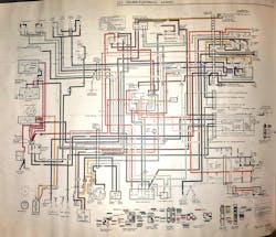
We are faced with a non-functioning headlight on a 1972 Oldsmobile Cutlass. We have already tried a new headlight bulb, and the headlight still does not work. What could it be? How does the headlight circuit function? Is there a fuse somewhere? There is no scan tool to help and no diagnostic trouble tree to consult on this old beast. We will need to check the circuits and components that supply power and ground to the headlight. In short, we need to look at the wiring diagram. Wiring diagrams have changed a lot since the simple single page wiring diagram of the 1972 Cutlass. But there are many diagnostics that techs are faced with today that are very similar to the issue with this old Cutlass. They require the interpretation of a wiring diagram.
When we look at the wiring diagrams, either factory or aftermarket, there is a massive amount of information that we can get from them, especially if we understand everything they are telling us. Wiring diagrams have become an important part of the day-to-day diagnostics in the shop. It seems like everything on today’s vehicles is controlled by a module or controller, and those devices require power, ground, inputs, outputs and communications networks for functionality.
Symbols and wiring diagram information
There are many different symbols used by the manufacturers to illustrate items in their wiring diagrams. Using our information systems we can easily find what these symbols represent and loads of other wiring diagram information.
There are many standard symbols used today that can display the type of signal or communications being used, if the wires are shielded, splices, male or female connection types, LEDs or photo diodes and often internal components of modules such as internal switches.
The wiring diagram will illustrate the type of circuit protection used in the circuit, showing fuses, fusible links, circuit breakers or the commonly used FET. The Field-Effect Transistor (FET) is often used as an integrated protection device on common electronic circuits.
When accessing the vehicle’s wiring diagrams using the popular information systems available today, there will be a hyperlink or menu item that will redirect us to the “wiring diagram information and instructions” section or the “how to use the system's wiring diagrams” section. Once redirected this will show information on just about every aspect of the wiring diagrams. This information will show the wire gauge, wire color, what the numbers by the wires are (usually circuit numbers), connector numbers, relay information and much more.
These sections will show the electrical schematic symbols, vehicle zoning and factory specific wiring diagram information. This is a fantastic resource that sadly most techs never utilize. The OEs supply the same information in their systems as well. Most OE and aftermarket wiring diagrams now supply hyperlinked information on connector views and locations when using the wiring diagrams, and this is very helpful.
Solid or dashed lines
When we see components and connectors in a wiring diagram that are outlined with a dashed line, this indicates that only a partial view is shown. The diagram is only illustrating the parts of the system that are involved in the circuit we are looking at. If the components and connectors in a wiring diagram are outlined with a solid line this shows that the entire component is being shown. Wiring diagrams do this to cut out any circuits or components that aren’t needed. This clarifies the wiring diagram making it more concise.
Follow the flow
When looking at how a wiring diagram is drawn, it is essential to understand how the power is going to flow through the circuits. Today's automotive wiring diagrams are almost always drawn with the power at the top, and the ground at the bottom.
Commonly referred to as “power flow,” it means that the power or voltage for the circuit is shown at the top. It then flows down through the circuits and components to the ground at the bottom. This may seem obvious, but it is often missed by many of today’s techs. Even the dreaded track wiring diagrams or DIN Standard diagrams (Deutsches Institut fr Normung e.V. Standards) that VW/ Audi have used for years are designed in the same way: power flows from the top to the bottom. Honda/Acura has switched to using a track style variation wiring diagram called EWD II (Electrical Wiring Diagrams II). It was designed to work better for their techs and the diagnostic tools and software they are using at the dealerships. The EWD II Honda/Acura diagrams use a power flow top to bottom design.
It is important to note that this power flow doesn’t just mean a traditional 12V system. The wiring diagrams of hybrids and electric vehicles are drawn the same, with the high voltage power supply at the top.
Using a wiring diagram to diagnose an issue
Let’s look at a simple wiring diagram for the A/C compressor clutch on a 2018 Chevrolet Silverado 1500 and see how it can aid in diagnosing an issue when there isn't a diagnostic trouble code to diagnose.
This Silverado has an A/C compressor clutch that doesn’t engage. We have installed the scan tool and A/C gauge set; there are no A/C-related codes and the AC pressure readings are good. We have decided to look up the wiring diagram for the A/C compressor controls for this truck and see what it tells us.
Looking at the wiring diagram we can see that we have B+ on the top of the diagram, and our ground at the bottom represented by the chassis ground symbol.
We can see the other controls, devices and circuits that are part of the A/C compressor operation. We want to find the components directly involved in the operation of the A/C clutch. To do this, we will follow the circuit from B+ to the A/C clutch then on to the ground to complete the circuit. You can do this by printing the diagram and using a highlighter or using the tracing feature on your information system. This will highlight the circuits we are concerned with.
When we trace or highlight, we will have the following components and wiring: X50A Fuse Block-Underhood, KR75 Engine Controls Ignition Relay, F35UA 10A fuse, KR29 A/C Compressor Clutch Relay, X2 connector, 459 WH/GY wire, 59 BN/GN wire, Q2 A/C Compressor Clutch, X1 connector, K20 Engine Control Module and finally the G110 Light Duty chassis ground.
Just looking at the wiring diagram has provided us with the information needed to start evaluating the circuit of the A/C compressor clutch.
The wiring diagram has shown F35UA as the single 10A fuse for the circuit found in position 35 in the X50A Fuse Block-Underhood that supplies power to the A/C compressor clutch.
It has also shown us that the power from F35UA for the A/C compressor clutch is controlled by the KR29 A/C Compressor Clutch Relay. For a relay to function it needs two sources of power: coil control power and switched power. The KR29 A/C Compressor Clutch Relay coil control power is supplied by the KR75 Engine Controls Ignition Relay. The KR29 A/C Compressor Clutch Relay activation is controlled by the K20 Engine Control Module, which supplies an internal low reference, turning on the relay. The ⏚ symbol is used, not the as there is a difference in the type of ground circuit used.
By looking at this electrical diagram we now know the location and type of circuit protection used, which is the F35UA 10A fuse. We know that there are two relays that control the power to the A/C clutch, and both are in the X50A Fuse Block-Underhood (the dashed lines around the Fuse Block show it’s only a partial view). We know where the A/C compressor clutch is grounded using a single black wire and could search for its location because we know its ground is G110. We know that the A/C compressor and A/C compressor clutch are a complete unit because of the solid line outline around it.
We know that the K20 Engine Control Module is going to supply a ground on the WH/GY circuit wire to activate the KR29 A/C Compressor Clutch Relay. The location of that WH/GY wire in the connections at both ends of the circuit are shown in the diagram. Note the dashed lines around the X2 and X1 connectors are only showing the location of the two-wires involved in the operation of the A/C compressor clutch.
Now we can start our testing after looking at and interpreting what the wiring diagram has shown us. We can start by checking the power supply and ensuring the F35UA fuse is OK. If the F35UA is OK we could activate the KR29 A/C Compressor Clutch Relay bidirectionally. This would prove that the K20 Engine Control Module and the wire 459 WH/GY are OK and functional. We would then verify that the KR29 A/C Compressor Clutch Relay can supply the needed voltage to the No. 2 terminal (59 BN/GN) wire of the Q2 A/C Compressor Clutch connector. If the voltage isn’t being supplied, but the relay is functional, we have narrowed down our areas of concern. It could be a bad relay, corrosion internally in the X50A Fuse Block-Underhood, bad connections at the X2 connector or an open in the 59BN/GN wire.
If voltage is present at the No. 2 terminal (59 BN/GN) wire when we perform the bidirectional test, we have verified the circuits from the F35UA fuse, down to the Q2 A/C Compressor Clutch. We would then only have to verify the ground circuit 550BK and G110 before we could conclusively decide that we have a bad Q2 A/C Compressor Clutch.
We can make these decisions and testing procedures based primarily on the examination of the wiring diagram of the A/C compressor controls of this truck.
Wiring diagrams aren’t going away
Just by looking at a wiring diagram we can learn so much about a system and how it works. We will find the power supply, the ground, the circuit protection, the connectors involved and the names of the components in the system. Looking at a wiring diagram is often the second step in a diagnostic process after the first step of attaching a scan tool and reading the DTCs. Knowing how to read and interpret a wiring diagram is a skill that is developed and honed over time as today’s wiring diagrams are getting more complex. But there is positive news. Learning and understanding how to read and interpret wiring diagrams is a skill that will be needed even more with the increased electrification of the vehicles that we are servicing.
About the Author

Jeff Taylor
Jeff Taylor is a seasoned professional at CARS Inc. in Oshawa with 40 years in the automotive industry. As a skilled technical writer and training developer, he holds licenses in both automotive and heavy-duty vehicle repair. Jeff excels in TAC support, technical training, troubleshooting, and shaping the future of automotive expertise.