Diverse methods for battery diagnostics
What you’ll learn:
- How to use a digital storage oscilloscope (DSO) to perform automotive battery analysis
- How to load test an automotive battery for valid condition analysis
- How to conductance test an automotive battery for valid condition analysis
As a public educator and technician, it is sometimes difficult to transfer immediate and advanced needs of the industry in instruction due to major diversity in methods of approach. Fortunately, a significant portion of the problems technicians face as part of their daily routine are fundamental in nature. This is where it becomes critical to develop and encourage personal understanding of fundamental principles related to electricity/electronics.
Given the initial fear new technicians may have of electricity/electronics, I’ve found it much easier to present systems and components that express the theory and operation of the following:
- Potential energy (battery, power supply)
- Circuit protection (fuses, circuit breakers, fusible links)
- Switching mechanisms (switches, relays, transistors)
- Conductors (wiring)
- Engineered load (headlight, solenoid, module, actuator)
While all have significant value in a well-engineered circuit, nothing sticks out more than the first item, potential energy. This is where practical battery theory, inspection, and service plays a key role in developing technicians who are competent upon entry into the workforce.
At the most fundamental level, a vehicle’s power supply must be in good working order to operate any component on a vehicle. Technician competency in battery analysis and appropriate testing methods must be top-notch upon entry into the workforce as many new technicians deal specifically with tire, battery, and accessory service.
Battery testing options
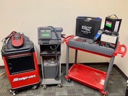
Variations commonly found amongst 12V batteries on the market are absorbed glass-mat (AGM) and flooded lead-acid batteries (serviceable and non-serviceable). While diagnostics are similar, service and maintenance vary based on accessibility and chemical/structural variances amongst each type. Common testing procedures I teach and rely on include the use of the following tools: digital multimeter; conductance tester (low amperage tool); refractometer (if battery is serviceable); load tester (high amperage tool); and/or PicoScope 4425A Digital Storage Oscilloscope (battery test option in PicoDiagnostics software). (See Figure 1).

Not all shops are willing to invest in such a broad array of tools for battery service and diagnostics, so it’s important to have a good understanding of all the options.
Digital multimeter (DMM) testing
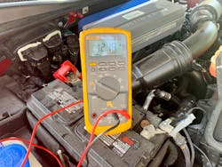
While DMM’s (Figure 2) do not provide a light-speed reaction to voltage variations based on sample rate, they do provide a stable enough reading to project static voltage, continuous declines in voltage, and charging system voltage output. One major issue to consider is where to make connection with the battery during such readings. In knowing that battery voltage is limited to connectivity between post and terminal, I recommend comparing post-to-post readings of battery voltage to post-to-terminal readings. Note that this process may be impacted by battery design, such as side post batteries.
While slight variances do exist amongst manufacturers to indicate a battery’s 100 percent state-of-charge, I typically project 12.6V is the norm (lead-acid). While cranking, a measurement of at or below 9.6V indicates severe battery degradation or poor maintenance, and further assessment must be conducted, such as charge and re-test following battery manufacturer’s recommendations, cell inspection (if serviceable), etc.
Conductance testing
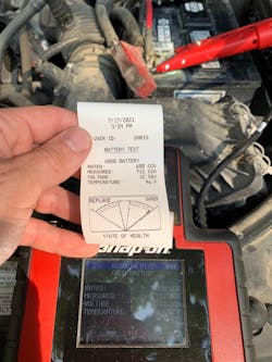
Conductance testers utilize battery source voltage to measure current and infer resistive values in a complex, yet simple manner. This technology is similar to the use of DMM’s when performing basic testing procedures (voltage, resistance, and current measurements) to mathematically project measurable outcomes. The major benefits of utilizing conductance testers to determine battery conditions are the tool’s cost and size. Conductance testers (Figure 3) are traditionally handheld, consume very little space, and are typically less expensive than dedicated carts used to assess battery condition. Conductance tester manufacturers currently equip their tools with exportable data files or immediate printable results to document battery condition at the time of measurement, and often include summaries of battery design, post arrangement (side/top/stud), voltage output, inferred amperage output, and battery condition based on tool analysis. This type of testing allows technicians to easily document their findings and display evidentiary results upon completing the test.
Case study: 2007 Chevrolet Impala
A customer came in complaining of a short crank but no start after extended time sitting — the car sat for four-plus months.
Because this vehicle had not been started nor driven in months, I verified the no crank/no start complaint. Turned the key and nothing! I popped the hood and used a DMM to check resting voltage on the battery. I found 4.13V — less than 30 percent of an expected resting voltage on a 12V (12.6V) battery. Knowing that flooded lead-acid batteries have memory issues if not maintained continuously, I jump-started the vehicle with a battery booster to measure charging system voltage with the DMM, finding 13.81V when running. After allowing the battery to charge, I ran a conductance test to determine the battery’s condition. After charging, the battery’s resting voltage peaked at 10.26V and only output 26 CCA’s. The battery was replaced and the vehicle operated normally.
Load testing
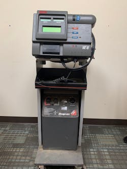
One of the most stressful ways to assess a battery’s condition is by loading it to the point of higher amperage output readings upon testing. Load testers can be handheld or cart based (Figure 5). They may also be equipped with analog and/or digital readouts that assist a technician in documenting raw, measured values that project battery condition. In a carbon pile test, the battery is forced to conduct through carbon elements under pressure to measure live voltage and/or amperage. As pressure increases on the carbon pile, resistive value decreases and forces the battery to exhaust itself of stored electrons in an effort to project how stress impacts the battery’s performance. A major concern of using such a stressful load on a battery is damage to the battery and the potential for injury if the battery were to fail under such a heavy load.
Follow the load tester manufacturer’s instruction to limit the potential for damage or injury when operating.
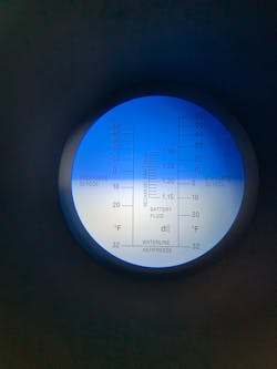
Refractometer (specific gravity) testing
While many newer batteries are not serviceable, technicians in the industry will still encounter batteries that have removable service caps. This option allows technicians to sample individual cell acid and assess the density for diagnostic benefit. To begin the process, the refractometer must be calibrated with a few drops of distilled water being placed on the clean sample plate. Once the hinge plate (also called a “daylight plate”) is closed, the technician needs to point the sample plate towards a sufficient light source and view the measured value on the display. If the display indicates the sampled water has zero acidic value (32-degree freeze point), wipe the plate clean and begin sampling individual cells in a similar manner. If the distilled water does not show zero acidic value, the refractometer must be calibrated to zero to progress (typically done with a small, flathead screwdriver provided by the refractometer manufacturer).
Fortunately for us, most vehicle battery specific refractometers provide text indicating “good”, “fair”, or “needs recharged” based on calibrated values (Figure 6). Result of this type of test may vary with calibration or sampling errors.
Case study: 2001 Ford Focus Wagon
This vehicle came in with an immediate no crank, no start concern. I popped the hood and verified battery terminal to post connection, measured live voltage values, and assessed the battery’s condition using a refractometer and load tester to document multiple methods of diagnosing battery condition.
Upon initial inspection, I found severe corrosion on the negative battery post-to-terminal connection due to sulfation. I also measured an unsurprisingly lower than normal battery voltage with a DMM at ~12.2V. In wanting to capture a diverse array of methods for verification, I decided to use a refractometer (as the battery was serviceable) and a load tester to demonstrate the benefit of both tools in service. When sampling the specific gravity of the battery cells, I found the specific gravity (density of battery acid in cells) to average ~1.19, which indicated low density (also indicated by initial DMM reading). The final step was to utilize the load tester. The battery was rated at 525 CCA’s, but when I applied the higher amperage load test, the battery yielded 300 CCA’s, further verifying results of the DMM and refractometer.
I replaced the battery and the vehicle’s operation returned to normal.
DSO diagnostics
As the industry continues to use advanced methods of testing, my personal preference for assessing a battery’s condition is the Pico Diagnostics Battery Test (Figure 7). This test centralizes the most comprehensive data, projects dynamically physical values of voltage and current, and creates a file that can be saved, printed, shared, and displayed for reference and illustration.
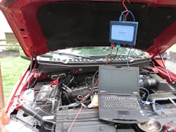
Case study: 2017 Ford F-150
This vehicle came in with a complaint of remote start intermittently inoperable after a long sit time.
The truck was purchased in 2021 with less than 20,000 miles on it from a local dealer (it sat for many months after the original owner purchased it). In wanting to gain familiarity with some embedded digital storage oscilloscope (DSO) battery test software, I decided to use this vehicle as a way to document the features of this tool for class use. To begin this test, I connected the DSO to a laptop, opened the software, filled in ambient temperature and battery specifications, connected the test leads as specified (voltage probes on battery connection points and 2000A probe around the starter M cable on channel 2), selected start on the software, then cranked the engine and gathered data/interpreted the results.
Findings from this test indicated my initial suspicion: the battery needs to be recharged and cycled normally. The battery output 1080 CCA’s, though rated at 880 CCA’s. Initial voltage while testing was 12.3V (40 percent SOC) but dropped to 9.07V when cranking, which is well below the industry recognized standard of 9.6V when cranking.
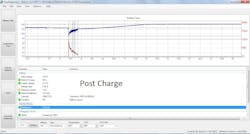
After cycling the battery and running a second test, (Figure 8) I found the battery’s output to peak at 1026 CCA’s, though resting voltage was raised to 12.6V (80 percent SOC). The software indicated the battery performed sufficiently and no longer needed a recharge for assessment.
Of the methods discussed and displayed above, I must state that two major tools used to assess a battery’s static and dynamic conditions have more potential in the field: digital multimeters and DSO’s. Both should be considered prioritized tools for technician ownership as they have the potential for use in many other mechanical and/electrical diagnostic routines.
I must note that while battery analysis may be prioritized by technicians when dealing with a slow crank, no crank, and/or limited accessory operation, a faulty battery can cause more severe symptoms and should not be overlooked when completing diagnostics for more difficult issues on any vehicle.
Tools used:
Digital multimeter
Conductance tester
Load tester
Digital storage oscilloscope (laptop, tablet, or handheld DSOs may be used)
Refractometer
About the Author

Chris Reynolds
Chris Reynolds is an ASE Master Technician, ASE-Education Foundation evaluation team leader, and an associate professor of automotive technology at Lewis & Clark Community College in Godfrey, Illinois. He is currently in his second year of study toward a Doctor of Education in Educational Practice degree at the University of Missouri – St. Louis. He enjoys time with his wife and three children and advocating for the needs of the automotive service industry and the field of technical education.