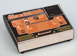
Is the coil good or bad? During the recent Automotive Aftermarket Parts Expo (AAPEX) Show in Las Vegas, Innova debuted its 4400 Coil and Control Module Tester, a counter-top diagnostic unit ideal for both shops and parts stores. The bench-top tester is designed to safely and easily test the circuitry of conventional ignition coils, coil-on-plug coils (COP), distributorless ignition systems (DIS) and electronic ignition modules (EIM).
The tester is designed for off-vehicle (countertop) diagnosis — OEM and aftermarket — and includes 27 custom-molded coil cables and 17 additional cables available for purchase separately. The 4400 tester simulates a variety of conditions to check for coil strength, primary winding, charging status, break current, firing order, start retard control, current drain, input thresholds, dwell time, tach/coil signal, saturation and output energy.
The tester displays complete and accurate pass/fail test results within seconds. The new 4400 also features a PC/printer link that enables you to print out a hard copy of all test results. The tester can also be updated/expanded via Internet downloads. In addition to having the capability to perform the needed tests, the unit’s software and PC-Link printouts can be customized (mini printer printout only leaves blanks to fill), and even monitors which technician is performing the tests.
The COP tester is able to perform a pre-test mode to check for connectivity, coil resistance, shortage, or open circuit of primary winding. Cranking rpm, idle rpm and high rpm tests check for charging, and break current, peak voltage, burning time, misfire and an ignition feedback signal. When a coil or expensive module fails, you have documented proof of the need to replace the part, which definitely minimizes the potential for trying to explain the need to the customer.
The comprehensive testing parameters not only serve to verify the condition of a coil or module, but aids in selling additional components, especially when a coil or module passes the tests.
In order to solve certain drivability issues, the tester may suggest other components such as cam or crank position sensors, spark plug wires, etc.
Using the tester
The 4400 tester offers a very simple and straightforward operation. The supplied power cord plugs into the rear of the unit, and plugs into any nearby 110-volt AC outlet. The on/off rocker switch is located in the rear, next to the power plug. Don’t power-up the tester until you’ve connected the coil or module to be tested.
A dizzying array of 44 cable adapters are available, covering just about anything you’re likely to encounter. Select the appropriate adapter harness for the coil to be tested (each adapter pin connector is numbered for reference). A reference lookup is provided to identify various coils and modules, allowing you to match up the correct harness.
A primary adapter extension cable is first connected to the tester. This is a male/female connector which then accepts any of the individual tester connectors. Plug the selected connector harness to the primary cable and to the coil or module to be tested. Make sure that each connection (male, female or multi-pin connector) is fully seated.
NOTE: I found that, in some cases, the connection between a test harness adapter and a coil terminal is on the tight side, which can make it difficult to disconnect the adapter after testing. I suggest applying a bit of dielectric grease to all ignition spark connections at the coil to be tested before connecting the test adapter to the coil. If the connection is really tight, you stand a chance of breaking one or more of the test adapter’s posts as you try to wiggle it loose.
Turn the power switch (on the rear of the tester) to the ON position. Simply press the START button to proceed with the test. The unit will progress through all test phases, with indicator lights blinking as the test continues (each test phase is printed on the unit face, next to its indicator light). As each test is completed, the green light will glow steady if passed, but the red light will glow if failed in each test phase. Each coil probe also features a handy viewing window, providing a visual confirmation that the spark is occurring.
[PAGEBREAK]
Once all parameters have been checked, a final test result concludes by a green pass light or a red fail light that illuminates at the right side of the tester panel.
Press the PRINT button at the right, and a detailed diagnostic printout will be presented.
A handy USB port and a miniport also are featured on the rear of the tester, for connection to an external PC, if so desired. Innova’s PC Link software allows you to view, log and print detailed reports. ●
TOOL SOURCE
INNOVA ELECTRONICS
17352 Von Karman Ave.
Irvine, CA 92614
(800) 544-4124
About the Author
Mike Mavrigian
Motor Age Editor
Mike Mavrigian has written thousands of automotive technical magazine articles involving a variety of specialties, from engine building to wheel alignment, and has authored more than a dozen books that crisscross the automotive spectrum. Mike operates Birchwood Automotive, an Ohio shop that builds custom engines and performs vintage vehicle restorations. The shop also features a professional photo studio to document projects and to create images for articles and books.

