Tips for maximizing scan tool use
Every journey begins with one single step. Some people take that step with their left foot and others with their right. Neither would be considered incorrect. One journey can be carried out a number of different ways. The point is, there is no correct or incorrect way to get to a destination, so long as you get there.
The same holds true regarding diagnostics, or more specifically, analysis. We can pursue a symptom from multiple angles. Some technicians have a well-developed seat-of-the-pants, instinctive-feel (probably developed from years of getting their butts kicked in the trenches of the automotive industry) and can be fairly accurate in their diagnoses. Other times, those same technicians make costly mistakes because no true testing was carried out. Some technicians begin and end their analysis with the scan tool and follow their instincts from there. They employ subsequent tests that focus more on a particular area of a system, perhaps giving them the ability to decide what can't be the source of the fault. This limits the amount of guessing.
The truth is, if you are not testing, you are indeed guessing. The scan tool provides us with a necessary and time-saving preliminary step. The information from the scan tool does more than display diagnostic trouble codes (DTCs). It can also show us what the electronic control unit (ECU) believes it sees, as well as its intent, or how it decides to control the components for the systems it’s in charge of. Following are some techniques I use to decide where I want to invest my allotted diagnostic time.
The entire story
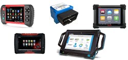
Let’s start with parameter IDs (PIDs). The PIDs a technician views will depend on a few variables – the first being your scan tool of choice (Fig. 1). Many of the PIDs found in the OBD generic portion of our scan tool exist because they are mandated to be there by law. Many times, we must view information that is more vehicle-specific, meaning we may have to view it from the enhanced side of the powertrain control module. Not all scan tools are built the same. If they were, we would have an extremely expensive device that could communicate with every node (ECU) on the network, and support every PID, as well as every bidirectional control. This is certainly not the case. I have a few scan tools I employ regularly. I find where one of them falls short, the other can fill in the gap.
Another variable is the loop-speed, or the speed in which the scan tool can refresh. When we select to view a set of PIDs, we are making an inquiry to the ECU for each PID we select. The ECU will have to process the request from the scan tool and then reference the inputs it’s processing from the vehicle. It will then report the data to the scan tool, where it’s processed and delivered to us for viewing. All of this takes time – the more inquiries we make, the slower the scan tool performs … so choose wisely.
Next, consider the vehicle system you are addressing. Some systems are simple and may involve one or two ECUs to carry out the process of opening and closing them. Other systems are very inter-dependent upon one another (like ADAS, traction control, or even HVAC) and require communication between several ECUs and many times over multiple communication networks (Fig. 2). I’m always looking for the scan tool to tell the entire story. I should be able to capture the inputs to the ECU, as well as the outputs to reflect what the ECU sees and if the ECU is trying to generate an output. The data should be collected in a fashion that a fellow technician could analyze the capture and make a diagnostic decision.
Last, but certainly not least, it helps to have a thorough understanding of the system and components that are being addressed. The ability to analyze scan data is just that. Without the understanding of system-configuration (all the players involved in carrying out a specific goal or output), there would be no understanding of which data PIDs were necessary to view. The decision about which of the PIDs to display will be derived from the information found by referencing a wiring diagram as well as the description and operation of the system. These PIDs will represent:
Inputs: Information about individual components’ physical state (pressure, temperature, angle, or position) and the intent of the ECU or person operating the system.
Decision making: This information, or processed data, is reflected by the ECU PIDs and indicates a state of operation (a “thumbs-up" or "thumbs-down,” if you will). They will typically be displayed as “on/off,” “yes/no,” “permitted/not-permitted,” etc. This gives us, as technicians, valuable insight.
Shared data: Many systems exist on a virtual platform, meaning their functionality requires a communication bus (or several) with integrity. If data that is being processed in a specific node is then reflected in the PID list of another node, this is a good indicator that the data is being shared over the network. This provides for a means to split the system into sections in which to troubleshoot. With a little common sense and knowledge of the previously researched system, a lot of unnecessary testing will be avoided.
Outputs: This is the result. Thinking in terms of a true "system," any breakdown in the above-mentioned will not allow for an output to occur. Seeing the entire story reflected in the scan tool list will show your intent to operate a system, the data required for an ECU to make a decision, and the final decision to operate or not to operate a component (and the reason why). Ask yourself, would you be thinking about testing a switched input (like a window switch) if the scan tool reflected a PID that showed the intent to lower the window?
One of the most valuable times to employ the scan tool is during drivability analysis. Just think of how situations can yield a “low-power” complaint. Inputs/processing/outputs … it’s the same for drivability. We typically reference the fuel trim values to reflect how well the engine is being fueled. This is the end result or feedback. When a vehicle fails to produce power, it’s because the engine can’t breathe properly, the air/fuel ratio is incorrect, or the ignition timing is not as it should be (or it is inadequate). With a properly set up PID list (in a graphed format) and running the engine under different operating conditions, it’s easy to determine the cause of the low-power complaint right from the driver’s seat.
Considering all this data is gathered right from the driver's seat; I can’t think of a more efficient way to begin a diagnostic approach.
For each vehicle that rolls into the bay, your scan tool can open your eyes to how all the players function together to carry out a goal. You get to see the entire story play out for you, so diagnostic direction can be gained before investing time in a specific area. Begin employing these capturing/analysis techniques on well-known vehicles and get comfortable with the functionality of your specific scan tool(s). Learn the ins and outs of it and what makes it special. You do that and watch how quickly productivity and confidence soar in the shop.
About the Author

Brandon Steckler
Technical Editor | Motor Age
Brandon began his career in Northampton County Community College in Bethlehem, Pennsylvania, where he was a student of GM’s Automotive Service Educational program. In 2001, he graduated top of his class and earned the GM Leadership award for his efforts. He later began working as a technician at a Saturn dealership in Reading, Pennsylvania, where he quickly attained Master Technician status. He later transitioned to working with Hondas, where he aggressively worked to attain another Master Technician status.
Always having a passion for a full understanding of system/component functionality, he rapidly earned a reputation for deciphering strange failures at an efficient pace and became known as an information specialist among the staff and peers at the dealership. In search of new challenges, he transitioned away from the dealership and to the independent world, where he specialized in diagnostics and driveability.
Today, he is an instructor with both Carquest Technical Institute and Worldpac Training Institute. Along with beta testing for Automotive Test Solutions, he develops curriculum/submits case studies for educational purposes. Through Steckler Automotive Technical Services, LLC., Brandon also provides telephone and live technical support, as well as private training, for technicians all across the world.
Brandon holds ASE certifications A1-A9 as well as C1 (Service Consultant). He is certified as an Advanced Level Specialist in L1 (Advanced Engine Performance), L2 (Advanced Diesel Engine Performance), L3 (Hybrid/EV Specialist), L4 (ADAS) and xEV-Level 2 (Technician electrical safety).
He contributes weekly to Facebook automotive chat groups, has authored several books and classes, and truly enjoys traveling across the globe to help other technicians attain a level of understanding that will serve them well throughout their careers.