Using diagnostic techniques to tackle electrical challenges
It used to be routine in our shop that I programmed modules for other shops and customers. I am not too sure where all that work disappeared to, but every now and again I get to do what I really enjoy. I‘m sure as you all have experienced, programming does not always go as planned. Programming modules can present some unique challenges with customer-supplied parts and/or improperly diagnosed concerns.
Test, don’t guess
More than once I attempted to program modules to vehicles that were not compatible. One of the most common situations I have run into was that the vehicle receiving the module was incorrectly diagnosed. After programming the replacement computer, the same symptoms existed that the replacement module was supposed to have fixed. Before programming a module, we would tell the customer up front that it was highly likely that whatever they were replacing the module for was not going to fix their concern. Oftentimes, it appeared as if they did not want to hear what we had to say. I think this was likely because they just spent $500 on a non-returnable module. Or, maybe their top Google search seemed more promising than the cost of diagnostic testing.If we kept our opinions to ourselves, and the customer-supplied part did not fix their concern, we could typically upsell them a diagnosis without hesitation. I never want anyone to waste their money with unneeded parts, but I really enjoy the diagnostic challenge after programming is completed. A 2008 Ford Expedition with 167,000 miles that came in with a complaint of erratic electrical component operation allowed me to tackle two of my favorite activities: diagnostics and programming.
Sometimes I think to myself, if I were to botch a diagnosis or a repair can I just tell the customer, “I'm sorry, but I'm just a practicing mechanic?” It seems like being a mechanic has a lot of similarities to being a doctor practicing medicine. There is a huge financial investment, a lot of special tools, and most of your career is spent educating yourself. And if you screw up, someone could die. Yet, for whatever reason, I have never seen someone barter with a doctor. I have yet to hear, "Wow that X-ray price is too much. I'm going across the street to doctor XYZ". I've lost count on how many times customers have bartered with our business for discounts. It seems like our knowledge, experience, tooling, and investments are completely overlooked. And then you see someone waste so much money throwing parts at their car because they have been ill-advised. I've run into vehicles that have had every part thrown at the car and they are at our shop for a last-ditch effort. After spending all that money they now having nothing left to pay for diagnostic testing.
Today’s challenge
Now and again I find customers like the one that brought in this 2008 Ford Expedition for us to replace a module he had diagnosed himself (Figure 1). He has the money to fix his truck, and he has the money to pay us to diagnose it. I'd like to think of this situation as my lucky pot of gold. Again, I get to program something, and then diagnose and repair their concern (if the programming of the replacement module doesn’t alleviate the symptom). I think it's supposed to go the opposite way (diagnose then replace and program). Google just hasn't quite figured out yet how to diagnose cars correctly.He came to us with a brand new Generic Electric Module (GEM) from the Ford dealer. At the time, I did not even know what his symptoms were. I was just told to program this module for the customer. I pulled out the IDS (the Ford factory scan tool) and the programming was successful.
As I backed the truck out of the shop, a host of symptoms were exhibiting themselves in the cluster. I started to interview the customer about what concerns he was trying to fix by replacing the GEM. There were several different reasons he listed including:
Misfires
Battery light intermittently illuminating
Inoperative 4WD
The customer already knew how to duplicate the concern and all I had to do was activate the 4WD switch on the dash, and it appeared to act possessed. I suggested that he had a network problem. I told him that I did not have any idea what was causing it yet, but I was pretty confident I could diagnose it. He approved the time to do testing and I knew I was going to have a lot of fun analyzing this vehicle.
Testing techniques that prove the fault
I owe credit to some talented technicians from whom I adopted the technique I’m going to discuss. This technique was shared with me by two different people: Robert Pleasanton and Paul Danner. When I first got into automotive diagnostics, I was soaking up every single Scanner Danner video on YouTube I could find. I owe him a lot! The fundamentals of analyzing circuits via inputs and outputs came right from Paul via YouTube. This knowledge paved the foundation for using this technique in network diagnostics.It was not until Robert made a post about this specific technique that I started using it on vehicle networks. I believe he had attended a class that this was presented at and decided to share some insight on how this could be applied to network diagnostics.
There are a lot of useful techniques that can be used in network diagnostics. Some of these techniques I find fruitful and some I don't see the benefit in because they are either specific to the protocol you are analyzing or very intrusive. I think we all find ourselves in a time crunch. This drives my interest in finding out the most about the network in the least amount of time. In my experience, one of the best ways to get that info is to use an oscilloscope on the bus that you are having issues with.
There are typically a few actions I will take before the scope comes out. First, I want to do a full vehicle scan to see what modules are setting network faults or not communicating. Knowing this information will help understand what modules and/or buses are being affected by the issue. The next action will be to research and comprehend the bus topology. This means understanding the description and operation. I will want answers to questions like:
How are the modules configured?
Are there multiple buses?
Are there gateways?
How do the modules on the bus wake up?
Answering these questions is often the most time-consuming part, but it is so critical in making good diagnostic testing choices. Once I know what modules are on the bus and where some of the components are located, I can make an educated approach on the fastest route to getting my scope leads on the bus wires.
For this vehicle, the fastest route was to use a break-out box at the DLC. The technique I am about to use applies to any wired bus network. This technique is not limited to the type of bus or if it is a single wire or dual wire bus. This is what makes this technique so valuable. To understand how this technique can be useful we must understand how bus biasing is created and affected by voltage feeds/grounds.
Knowledge is power
Voltage divider circuits are going to be used to demonstrate how a module bias or reference voltage can be created. In a voltage divider circuit, there are two resistors in series called r1 and r2 that have current flowing through them between a power source and ground (Figure 2). The resulting “Voltage OUT” can be used to provide a steady reference voltage supply for onboard sensor circuits or even a bias voltage for signals to ride on top of. Voltage source and ground are an integral part of the equation in generating the voltage OUT. The mathematical equation for this circuit is:V_OUT = V_IN*r2/(r1+r2)
To generate a 5v reference voltage we would need 12v as our potential from positive to ground; and resistor 2 as 10 ohms and resistor 1 as 14 ohms. Plugging this into the equation, we would get V_OUT=12*10/(10+14). Processing this equation reveals a voltage out of 5 volts. So at this point, you may be wondering how is this is going to help you fix a vehicle. Let's look at this scope capture from this broken truck and use what we know about a powertrain CAN bus to decipher what may be wrong with this vehicle (Figure 3).
As I mentioned earlier, I was able to capture this data via the DLC under the dash. What we know from known-good CAN data bus captures is:
CAN_HI will rest at 2.5v and be pulled high to 3.5v during data transmission
CAN_LO will rest at 2.5v and be pulled low to 1.5v during data transmission
The recessive bias of the network is 2.5v, meaning this is a flatline voltage that represents no data transfer. As soon as a module on the network attempts to transmit data, is when we see a square-wave-looking pattern. What we can see during this capture is that the resting bias is sitting around 3 volts (Figure 4). I am not splitting hairs by telling you that there is a serious difference between 3 volts and 2.5 volts. What this represents to us diagnosticians is the likelihood that a module on the network or multiple modules on the network have a poor ground reference. One of the other common possibilities is that a module has an open ground circuit inside of it. So how can a bad module or faulty ground to a module elevate a bus bias? Why does this happen?
I used to wonder about this for a long time when I saw elevated 5v reference circuits. All I knew was that there was likely a bad ground for the computer emitting the reference voltage but I couldn't necessarily explain why mathematically or using electrical theory. I told myself, "Well, I know the ground is needed to lower voltage from 12v to 5v, so it makes sense." This common-sense approach wasn't enough for me; I needed a more concrete answer. The voltage-divider circuit and equation will help us analyze why this happens (Figure 5). Let's play with some numbers here to see how we can manipulate the equation to gain some understanding.
If reference to ground is lost for a module we can say that we have a voltage drop or high resistance between the module and where it receives ground. In the equation what we can do to simulate this is to change the resistor value (r2) that is closest to the ground path to higher resistance. In our previous equation, r2 equaled 10ohms. Let's double that number to 20 ohms and plug it into our equation. V_OUT=12*20/(20+14) comes out to 7.059v. This extra resistance added to r2 has raised our generated bias from 5 volts to 7.059v.
Now that I know why a faulty ground or module can elevate a bus bias, I still need to diagnose this car. There are a couple of ways that this can be accomplished. I took the easiest approach that I could, which was to go back to my customer interview. The customer told me how to duplicate the concern. I knew that if I turned the 4-wheel drive switch weird things would happen. So I needed to look at the 4WD circuit. As I analyzed the circuit I found what grounds fed the 4WD module.
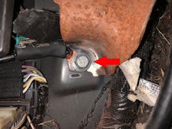
I gained access to the 4WD module, which was behind the glove box on the right side of the dash. I performed a voltage drop test from a known-good ground (the battery cable in my voltage drop test) to the grounds terminals at the 4WD module. I found the ground (on terminal 3 of connector C281B) having a 2.5v drop (Figure 6). This voltage drop was certainly way too high to provide enough current to operate the loads that this module controls (Figure 7).
I continued to do more research and decided to trace the module ground back to its termination point which was in the left-front kick panel area. As I removed the kick panel I immediately saw the problem. Ground G203 was no longer with us (Figure 8). The Midwest salt baths and our crazy winter wonderlands took a toll on the bottom of this truck. The fix for this was not expensive or difficult. I had to cut the wire back enough to get some decent copper exposed. I then added a new section of wire and a new eyelet to the ground. I ended up cleaning off the parking brake bracket and relocating G203 there as a sufficient reference to ground (Figure 9). There was no clean metal anywhere near the original location to reattach the ground too.
Note: It is not recommended to re-engineer circuits. It is extremely important to verify the supplemental or replacement ground location point is adequate for the amount of current flow the circuit is intended to carry. Failure to supply a sufficient ground location point can lead to unwanted circuit voltage-drop and a potential fire hazard.
I do not want you to walk away from this article thinking that I am some voodoo scope magician. My scope skills are average, at best. What I do have is some knowledge that I have gained from some seriously skilled diagnosticians/instructors and a little bit of curiosity to understand electronics at a different level. When we apply what we know to other diagnostic techniques we can see some awesome results that do not take much time at all.