We are getting closer to the 2022 model year vehicles that are planned to roll out as early as July 2021 for some manufacturers. It is important to understand that it will be the start of the new era of road technology as all 2022 vehicles produced in our country must be equipped with long-range radar to provide Automatic Emergency Braking. This is part of a mandatory commitment that was pushed by the National Highway Traffic Safety Administration (NHTSA) in 2018. The Federal Communications Commission (FCC) has also stepped up to the plate to require all long-range radar systems to phase out 24 GHz systems and be replaced with 77 GHz systems by Jan. 1, 2022. There will be a need for front radar systems to have a better range and velocity resolution that are more accurate in detecting objects in the roadway. By using the higher resolutions, it would be more precise in determining multiple objects in the roadway at the same time. The 77 GHz technology also allows for reduced size and form factor of the radar housings that will give the manufacturers smaller places to mount them in the vehicle.
It’s all about saving lives
The whole concept is to prevent rear-end collision on the roadway as well as front-end collision with pedestrians and bicycles. It is reported that 29 percent of crashes are rear-end collisions and of those about 87 percent are because of distractions. This does not include pedestrian and bicycle accidents. There needs to be a redundancy implemented that will aid a driver in lowering his or her chances of being involved in these types of accidents that cause harm or death to parties involved. It has always been a safety factor for automobiles and it dates back to the early days when seatbelts were mandated in 1968. Then came the age of computers that found their way to the automobile engine and braking systems. Antilock brake systems eventually joined the same network as the computerized fuel injection systems to control electronic throttle control and brake apply, through bussed communication. As time went on and things got a little more sophisticated, it was later mandated to be implemented as a new safety system with combined electronic stability control in 2013. Before this, it was also mandated to have tire pressure monitoring systems in all vehicles in 2008. It is all about saving lives so get ready for AEB to visit your service bay soon.
In a previous article, “ADAS curveball,” June 2020, I talked about a radar calibration I performed on a Jeep. It required a dynamic drive procedure to horizontally calibrate the long-range front radar system. It was first statically adjusted for proper vertical alignment, using a bubble gauge. Dynamic calibrations (for most manufacturers) require a straight roadway that you can perform a constant drive above 35 mph without stopping. You need to maintain a three to four vehicle distance and choose an area with many road obstacles on the side roads such as trees, utility poles and curbed signs. This is not the case for most manufacturers that do not use the dynamic calibration method. These manufacturers have the technician perform the vertical and horizontal calibrations statically in a bay. This practice keeps the tech off the roadway, especially if driving conditions are bad or highway access is too far from the shop.
The first contestant
I was recently called to a body shop that finished repairs to a 2018 Honda Accord that was involved in a front-end collision. The vehicle was post-scanned and cleared of any error codes stored in memory. There were no lights on the dash and the vehicle had no noticeable underlying issues. The car was released to the customer and after a few days, the car returned to the shop with a “Collision Mitigation Braking System Problem” message on the instrument panel (Figure 1). The vehicle ran and drove fine, but after driving the vehicle on the roadway the customer noticed the error message. When I arrived at the shop, I scanned the vehicle and pulled a code from the Driver Support System: P2583-76“Misalignment, Millimeter Wave Radar.”
I explained to the shop that the front radar system was out of calibration and the fault was created when the vehicle was driven down the roadway looking at vehicles and objects in its path. The only resolution would be to set up my equipment to calibrate the front radar system. I had to make sure the shop was a good candidate first. The shop floor had to be level, not pitched, and with at least a 30-foot-deep bay for vehicle and target setup. There also could be no objects out in front of the vehicle. I always try to point the vehicle out a large open bay door because it is required to have about 33 feet of open area in front of a vehicle and a width of about 13 feet, so it ensures no unwanted obstructions. Given the average length of a car to be at least 18-20 feet, it would almost require a bay to be about 50 feet deep and most shops may not meet the criteria. The other important factor is to place a level on the vehicle sill plates to make sure the vehicle itself is level, in case there are any suspension or tire issues
(Figure 2).
Once that preliminary criteria about the bay and vehicle have been fully verified, you’ll need to establish a centerline beneath the vehicle that extends out the front. I started at the rear of the vehicle, referencing from the emblem, down to the floor using a plumb bob. This will locate the spot to place a laser target (Figure 3). Next, I placed the plumb bob at the front of the vehicle, referencing from that emblem as well. In this case, I used a five-point laser directly under the plumb bob. This sets a red laser point on the floor, below its housing (Figure 4). Once my laser was set, I rotated its housing which lined up its laser to hit my rear target, under the vehicle (Figure 5). At that point, I had a laser centerline from the rear of the vehicle, that extended out past the front of the vehicle.
The target placement had to be determined by measurements given by the manufacturer. These measurements may not always match every year make model vehicle because each manufacturer has its unique systems or targets that they may be using. On this vehicle, you must first set the center of the cone height of the factory radar target. It must match the center of the radar housing’s distance to the floor. Then you need to measure out 4 meters/157.5 inches from the center of the left front wheel, out to the front of the vehicle, intersecting with the vehicle centerline (Figure 6). Once the target spot is marked on the floor, you place the target so the cone is perfectly centered (horizontally and vertically) over the mark (Figure 7). The target setup is the hardest part of the job but once you are done it is only a matter of commanding the onboard radar system to hit the target using a scan tool.
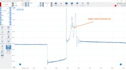
When I commanded the radar to hit the target, I received a reading of +4.80 vertical degrees and -2.29 Horizontal degrees (Figure 8). There was something seriously wrong because the final reading should be +/- 0.1 degrees or somewhere close. When I see a reading beyond +/- 2 degrees I usually look for a radar bracket or bracket support displacement issue.
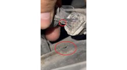
I took a close look at the radar housing and you can see that there is a common pivot point at the lower-left side of the housing, and 2 adjusting screws (Figure 9). The upper left is for vertical adjustment and the lower right is for horizontal adjustment. When I went to grab the radar assembly, I discovered that the pivot ball had popped out of its plastic seat, so I snapped it back in place.
I proceeded to perform a second check of the radar housing after it was snapped back into place. The resulting reading was close to specification at +0.39 vertical and -0.29 horizontal (Figure 10). From that point, I tweaked each adjustment screw until adjustment was within the specification of +/- 0.1 degrees and I was done. I told the owner of the shop to take time (when traffic would allow him) to test its operation on the highway. This job was performed around rush-hour and being in New Jersey, you need to choose an appropriate time and specific roadway where you will not be crawling in traffic.
The Honda and Acura radar systems that use plastic housing retainers can easily be damaged in an accident and may not be able to hold the radar housing properly in place. This simple $5 part can hold up the whole job. As a precautionary measure, I now keep these retainers in stock, and they are available from the Dealer with the part # 368-TLA-A01 (Figure 11). I would like to add that before performing a radar calibration it is probably a smart idea to physically check the radar unit for structural damage or mounting issues. It may save a lot of time, especially if an installer is not aware of what the component’s function is or how the critical mounting procedures affect the safety of the vehicle occupants. My only hopes are that this article has enhanced what you know or allow you to realize what you don’t know about long-range front radar systems.