Starter operation through the eyes of the scope
Content brought to you by Motor Age. To subscribe, click here.
What you will learn:
• Preliminary engine diagnosis does not require disassembly
• Cylinder integrity, starter motor, and related circuitry health can be determined with non-invasive testing
• The oscilloscope and amp probe holds much diagnostic value and offers a quick return-on-investment
The most efficient way to diagnose a starter circuit is by using an inductive high-amperage clamp and a lab scope. If you’ve been a technician for any length of time, you’ll likely relate to this scenario. A customer places a call to your shop and speaks to an advisor. The customer says he has a minor annoyance with a message from his driver information system on the instrument cluster. For peace of mind, he’d like to have the issue researched and checked out.
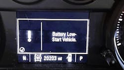
In our customer’s situation, it is the “Battery Low – Start Vehicle” message on his 2021 Chevrolet Silverado LT 4WD 5.3L Trail Boss Z71 with 20,203 miles on the clock. This engine has never failed to start, and the customer states that this message is very intermittent. He also adds that he has only witnessed one “slower than normal” engine cranking event so far (Figure 1).
The repair order ends up in your hands. Where do you start with such an ambiguous request? Wouldn’t you like to be able to go the farthest and the fastest with testing this issue so you can get to your next repair order?
This brings up what can often be a challenging situation: how to properly charge a customer. What can a customer expect to pay for a service and/or checkout that might produce no definitive action plan? Or find a problem? And how should a shop charge a customer for a check-out like this?
I believe we all too often make this a much harder situation than it must be. As business owners or professional technicians, we must be very good at communication and should always be honing that craft. Besides, we might repair automobiles, but we are in the “people” business, too. It's my opinion that the terms of service should be discussed upfront. Most customers do not like to work for free in their positions at their jobs. And since the larger part of our economy is driven on a fee-for-service basis most customers should expect to pay at least a nominal fee for a service.
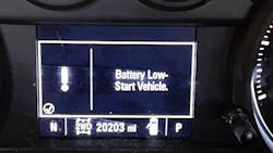
If there is not a clear resolution at the end of testing, what did they receive? They know that a series of components in the system in question have each been thoroughly checked by an automotive professional. Additionally, they now know what is not causing the issue they are experiencing (Figure 2). Diagnosing an issue is a process of elimination in most cases. Back to the diagnosis.
Having a mobile diagnostic and auto repair business has its pros and cons:
The pros:
- You always have the “largest” bay
- There isn’t a phone ringing off the hook in the shop
- Other distractions are also at a minimum because you are on your own
- You are not tied to the shop
It cuts out one of the largest objections in the sales process, which is the inconvenience of taking your vehicle somewhere for service.
The cons:
- You must keep all your tools and equipment put away, clean, and accessible always, no “Friday” drawers, guys and gals.
- Sometimes a vehicle’s location isn't convenient or safe to be repaired e.g., steep driveways, dangerous streets, or roadways.
As luck would have it, I was able to look at this customer's vehicle inside the warehouse where he serves as manager.
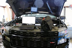
I arrived at the customer's appointed place and time and gathered the keys to the vehicle in question. I asked the customer some additional closed-ended probing questions and approached the vehicle in question to begin my diagnostic process (Figure 3). While at the vehicle, I did my best to confirm the customer's complaint (remember, it’s an intermittent issue).
If I left the driver's door open for more than approximately 30 seconds, the driver's information system would display (as he had described) a “Battery Low – Start Engine” message. At the time of system testing, the ambient air temperature was 29 degrees F. After I verified the complaint, I performed the next step in my action plan, which was to research existing recalls and technical service bulletins for this vehicle’s VIN. I found that there were no safety recalls and no technical service bulletins that were germane to the customer's complaint or symptom(s).
Follow the data
I know that some will say I’m preaching to the choir on this point I’m about to share, but I am going to say it anyway. Any diagnostic challenge, especially one that's electrical in nature, and on a modern vehicle should start with a baseline system voltage recording and battery health check, including a load test.
What’s included:
- Visual inspection of the terminals for corrosion and terminal integrity or looseness
- Visual inspection of the battery for acid leakage
- An attempt at gaining the manufacturer date from it
- Performing a computerized battery test using a tool that is of higher quality.
I begin here, because I know how easy it is to sometimes get ahead of myself in the diagnostic process. Even with 32 years of experience in the automotive industry, I will still sometimes inadvertently self-sabotage. Whiteboarding a brainstorming session and laying out in dry-erase ink what you’re going to test, and what you’ve already tested is a great help. Most of what you will add to your clock when diagnosing a vehicle is often stacked up with things you’ve checked already (or wasted time on). Take notes, record measurements, and be a professional.
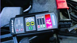
I own and use the Midtronics PBT-300 handheld battery, starting, and charging system tester (Figure 4). The factory rating for the battery in this vehicle was 800 cold-cranking amps (CCA, and it tested sufficiently at 727 CCA. After confirming the battery was within specifications, and since the vehicle’s engine cranks and starts currently, I move on to testing the motor side of the starter circuit, using the PicoScope 4425A and the Pico 0-2000 A inductive clamp.
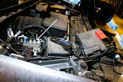
The vehicle's positive or negative cable can normally be used to perform the starter current draw and health check because the current is the same anywhere in a series circuit. This Chevrolet will have to be tested using the negative battery. The positive cable is not easily accessible, as it has a giant plate engineered on it (for a junction block and fusible plate, Figure 5).
Attaching the PicoScope inductive clamp is straightforward. The arrow on the clamp faces toward the direction of conventional current flow and will be drawn on the scope in a positive amplitude to display an increase in current flow.
Don’t worry if it is not connected in this preferred direction. Because the probe is connected non-invasively, you are not going to hurt anything. The trace will simply display invertedly. I connected it backward the first time and the trace is upside down (Figure 6).
The PicoScope lab scope is a robust unit and very forgiving to the apprentice-level technician. Using the guided tests portion of the PicoScope 7 software will take you step-by-step through connecting the scope and leads properly (Figure 7). Once the scope is attached the testing usually takes just a few minutes. The PicoScope 4425a has intelligent probes that set their parameters automatically. Simply connect them to the scope and they self-identify.
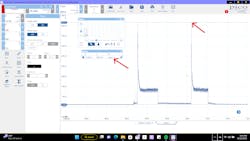
Per service information, placing this Chevrolet in clear flood mode is easy enough. You push the accelerator to the floor and crank the engine over. By doing this you are indicating to the computer to reduce the injector pulse. This should prevent to engine from starting. This waveform is produced while cranking the engine with the accelerator pedal depressed to the floor (Figure 8).
Analyzing the data
There are two cranking events shown in Figure 8. Each event was approximately 10-15 seconds in duration. Take notice of the inrush direct-current (DC) spikes at 908.1A. Some might say that it is too high, but I don't believe this is an issue as it occurs for only a short period, and it's consistent with the first cranking event of a normal operating system. Getting the engine to turn (from a stop) is more of a load on the starter than it is to keep the engine turning.
Something else to consider. A modern lab scope is among the most sensitive and accurate testing equipment we use in the industry. It displays a lot more resolution of the circuits’ electrical activity than other equipment (with a slower sample rate) would. This information can be used to gauge the health of the battery, the starter circuit, and the starter motor’s integrity. The highest delta amperage (or difference in amperage, between the upper and lower peaks) measured on continuous current flow, as the engine is being cranked over was 186.7A, and this is within specification (cursors are not being displayed to demonstrate in this capture). This number combined with the other known measurement of 10.5V (while cranking) can give you the dynamic resistance value of the entire starter motor circuit.
We’ve all seen Ohm’s law equation of V = I x R, or put another way, V = A x R. To work/solve any electrical problem backward, you only need two of the three factors. It can trip a lot of technicians up, so I always use an Ohm’s law calculator (which can be found on the internet). For instance, when entering the cranking voltage of 11V, and the current flow of 186.7 A, the resulting dynamic resistance is .058 ohms (which translates to 2053 watts of power used), and this information is valuable (power= voltage * amperage).
Let’s say when you cranked the engine over, the average available voltage was 10 V, with 500A of continuous current flow, yielding 0.02 ohms of dynamic resistance. This shows a tremendous load on the starter motor. At that amperage, you are more than likely to hear a horrendous noise from the starter motor, and it may physically rotate the engine much slower. At that measurement, it is taking 5000W of power to move the starter armature.
Inferred engine health
The other measurement you will see is the engine rpm. This is because using the vertical cursors to demonstrate the time difference between them can yield the cycle time (or the time it takes the engine to rotate 360 degrees). In this hypothetical, you'd see a much lower number than what a known good would have displayed. Our testing displayed 218.9 rpm. Depending upon the starter construction type (gear reduction, direct drive) you can have a slightly different reading on this. However, in most cases, you will see a known good engine RPM between 175-230 rpm.
The best way to describe what you are seeing when using a lab scope is voltage, amperage (or whichever domain is being measured) being displayed over time. Having a lab scope in your arsenal is a must-have for any technician that performs any electrical diagnostic work.
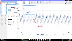
In Figure 8, although the data is captured, the large time base makes it difficult to see the actual measurement. We are going to zoom in and see how we were able to determine with the scope, that the engine’s cranking speed was 218.9 rpm. Zooming in to capture less time on the screen displays more valuable information about individual cylinders’ compression, and the effects it had on the starter circuit (Figure 9).
We are testing an eight-cylinder gasoline four-stroke Otto Cycle engine (named after the man who invented the technology). All we must do is use the graphing/measurement portion of the PicoScope 7 software and measure out four compression events. Considering this is an eight-cylinder engine, half of the engine’s eight cylinders completed a compression stroke in 360 degrees of crankshaft rotation (one rotation of the crankshaft, hence the cursors spanned to measure only four relative-compression peaks).
This scope allows multiple testing vectors all at once. By using this testing method, you can also determine if the engine has any possible mechanical issues, like compression loss. A scope is not a crystal ball, but it’s pretty close.
One PTEN (Professional Tool & Equipment News) contributor, Mario Rojas, of Super Mario Diagnostics, has said before that he uses a clear-flood cranking cadence and relative compression test on virtually every vehicle he looks at. One main reason is efficiency, as this test gathers so much pertinent information in the diagnostic process. On a misfire diagnosis, these tests are invaluable. It can help identify a compression or mechanical issue without any engine teardown.
Practice makes perfect
If you are lucky enough to work at a shop that provides a lab scope, or you’re lucky enough to have purchased a lab scope of any channel count or quality, use it often. The best way to get better at using any tool is to attend as much training as you can for its operation and use it often. Use all resources available. You will only grow as much as you are willing to sacrifice. Meaning, read magazine articles like this one. Read and invest in yourself.
If your shop doesn't offer to pay for your training, pay your own way. After all, your skill is a highly sought-after commodity. It can only be of benefit to you and your future. I also recommend getting to know your scope better by gathering known good waveforms and using those to build a library of them.
If you are a technician and you have spent your valuable time reading this, thank you; you are appreciated. I hope that you have found it of value and that it was enjoyable. If you are one of the many customers we have the privilege of serving every day in our shops, I hope you have gained perspective of what we attempt to do every day, which is to do the very best by you and fix your vehicle right the first time. We appreciate you!
In my customer's case, after some additional probing questions, he said his vehicle had sat in his garage for 10 days while he and his family had been on vacation. He had started it when he came home and didn't see any warning lights. By his own admission, he wasn't looking for any, either.
After sharing all the diagnostic data recorded, I advised he add a battery tender if he was going to continue to leave it to sit for any extended length of time.
Remember when diagnosing, if you hear hoofbeats, it's probably a thoroughbred and not a zebra. Just a fun way of sharing Occam's razor.
About the Author
Robert Stage
Robert E. Stage Jr. is a veteran of the automotive industry and has worked in multiple positions over the last 32 years. He and his wife, Cynthia, live in the greater Columbus, Ohio, region, where they own and operate Stage1Mobile Diagnostic and Auto Repair, a mobile automotive diagnostic, programming, and repair business.
He and his wife have four grown children. In his spare time, he likes to read, watch movies and documentaries. He likes to try new restaurants and explore new cuisine with his wife. Robert is very active on LinkedIn and participates in the Ted Ings Fixed Ops Roundtable advisory panels that are produced four to seven times yearly. These panels discuss the challenges and triumphs of the service department side of the dealership life and lifestyle. They also discuss mobile service as an emerging service option for clientele.
In the future, Robert expects to write more often and possibly pursue teaching automotive technologies across many formats.
